
Videos
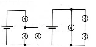
Both circuits al right have more than one path for the current. Sketch all possible current loops on the diagrams. (A “current loop” is a single path of conductors that connects one side of the battery to the other.)
For each of the current loops you have drawn, calculate the sum of the potential differences across the bulbs in that loop. (Use the measurements you made above.)
How do the sums of the potential differences across the bulbs in each loop compare to the potential difference across the battery?

Learn your wayIncludes step-by-step video

Chapter 6 Solutions
Tutorials in Introductory Physics
Additional Science Textbook Solutions
The Cosmic Perspective
The Cosmic Perspective Fundamentals (2nd Edition)
College Physics: A Strategic Approach (4th Edition)
Physics for Scientists and Engineers: A Strategic Approach, Vol. 1 (Chs 1-21) (4th Edition)
College Physics
The Cosmic Perspective (8th Edition)


- 9 V B. The circuit at right is made from an ideal battery connected to 4 ideal resistors as shown. i. What is the total resistance of this circuit? Show your work. R4= 352 R1 = 152 R3 = 452 ii. Find the current through each of the 4 resistors. Show your work. R2= 752 iii. Rank the potential difference across the 4 resistors from greatest to least. Explain your reasoning. iv. If resistor R3 is cut out of the circuit, without replacing it with anything, will the current through resistor R2 increase, decrease, or stay the same? Explain your answer or show your work.arrow_forwardA circuit has 3 resistors connected in parallel to a 75 V DC source. The resistances are 120, 100, and 12 Ohms, respectively. Draw the circuit diagram in the paper that will show your work. Use the correct units. What is the equivalent conductance of the circuit? What is the current through Resistor 1? What is the current through Resistor 2?arrow_forwardFor the circuit below, where each resistor is 100Ω, what is the total resistance of the circuit? If thebattery is 9V, what is the current supplied by the battery? Show your work and reasoning. [Redraw the circuit as necessary. Refer to the labels in the diagram for all calculations.]arrow_forward
- In the circuit below R1 = 20 and R2 = 9. Find the values of the unknown current and the battery voltages. Show your work clearly. The equations are easy to solve so I expect actual values for the answer. (Do not simplify the circuit) (Put the value of €2 in the answer box.) 81 62 0.1 A R1Q 0.175 A V R2 0 Answer:arrow_forwardFor the Electrical Circuit shown, calculate the current running through each resistor . You will need to sketch and/or label the resistors so I can interpret your results. Show the voltage drop across each resistor, also. This requires consideration of a parallel and series resistors together. Solve for the overall resistance of the parallel resistors, then put it in series with the other. Eventually solve for the current in each of the parallel resistors. Sketch: S Ohms 3 Ohms 6 Ohms 12 Varrow_forwardAnswer the following. Write your solution and box your final answer on each question. 1. What charge flows past a point in a wire in 6.0 s if the wire carries a current of 2.0 A? 2. If a circuit element can withstand a maximum current of 15 A, how many electrons can pass through it each second?3. How many electrons are transferred in a 10.0 A current that runs for 3.0 s?4. If 2.00 × 10²mA of current flows through the filament of a light bulb, how many electrons would pass through the filament in 30.0 s?5. What feature of a river is most similar to current in an electric circuit? (A) The depth of the river measured in meters (B) The temperature of the water measured in degrees Celsius (C) The vertical drop between two points along the river measured in meters (D) The volume of water moving past a point measured in liters per secondarrow_forward
- Solve what is belng asked. Show your solution in the space provided and double underlined your final answer. .s)Consider the circuit shown below. The terminal voltage of the battery is V = 18.00 V. (a) Find voltage across each resistor. the equivalent resistance of the circuit. (b) Find the potential difference across each resistor. Consider the circuit shown below. Find the R2 20 kS2 R1 = 4.00 2 R3 = 10 kf? 5 kl2 V = 18.00 V R, = 1.00 () V, = 12 V V, = 24 V R3 = 4.00 2 R.-- 10 kl2 Rs - 15 kl2 5) Consider the circuits shown below. What is the current through each resistor? R = 2 kl2 こV」 - 1.6 V V2 1.4 V R2 - 1 k2 R3-1 k2arrow_forwardDirections: Read and analyze the following problems, consider the two figures at the next page. Answer them properly and show your ENCODED SOLUTION. 1. For figure A: Using Ohms Law, calculate the equivalent series resistance, the series current, voltage drop and power for each resistor in the following resistors in series circuit. 2. For figure B. Find the total resistance, RT of the following resistors connected in a parallel network.arrow_forwardImagine you wanted to light a small light bulb using the wires and batteries from your lab exploration. On the following diagram of a light bulb, sketch how you would connect the circuit (i.e. draw the batteries and wires). Explain your reasoning. Now sketch a scenario with your wires and batteries that would NOT light the light bulb. Explain your reasoning.arrow_forward
- Consider the circuit configurations below, where two lightbulbs are connected to a single battery in different ways. Based on what you learned about parallel and series connections in lab, which of these two configurations would result in the light bulbs being the brightest? Fully explain your reasoning. Imagine that you are given four 100Ω resistors to build a circuit. Your challenge is to use all four of the resistors in the circuit, but the circuit must have an overall equivalent resistance of 100Ω. Is this possible? If so, draw a diagram of the circuit and explain how the connections result in a 100Ω equivalent resistance. If this is not possible, draw a diagram of a circuit involving all four resistors that has an equivalent resistance as close to 100Ω as is possible.arrow_forwardHow will the brightness of bulbs A and B change if bulb C is unscrewed? Will the result be different if bulb D or E is unscrewed instead? Explain. 7. Consider the circuit shown on the right. Are the bulbs C, D, and E connected in series, parallel, or neither? Explain. Parallel b/c the junction point is above point D where the current spreads a. Rank the bulbs in order of bright- ness. Use the symbols =, . Explain your ranking. b. с.arrow_forwardSet up the circuit shown at right. Before making voltage measurements, predict the ranking of the voltage across the battery and each bulb. Explain your prediction. Measure the voltage across each element.arrow_forward
 College PhysicsPhysicsISBN:9781305952300Author:Raymond A. Serway, Chris VuillePublisher:Cengage Learning
 University Physics (14th Edition)PhysicsISBN:9780133969290Author:Hugh D. Young, Roger A. FreedmanPublisher:PEARSON
 Introduction To Quantum MechanicsPhysicsISBN:9781107189638Author:Griffiths, David J., Schroeter, Darrell F.Publisher:Cambridge University Press
 Physics for Scientists and EngineersPhysicsISBN:9781337553278Author:Raymond A. Serway, John W. JewettPublisher:Cengage Learning
 Lecture- Tutorials for Introductory AstronomyPhysicsISBN:9780321820464Author:Edward E. Prather, Tim P. Slater, Jeff P. Adams, Gina BrissendenPublisher:Addison-Wesley
 College Physics: A Strategic Approach (4th Editio...PhysicsISBN:9780134609034Author:Randall D. Knight (Professor Emeritus), Brian Jones, Stuart FieldPublisher:PEARSON