
Concept explainers
Videos
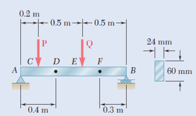
The beam AB supports two concentrated loads P and Q. The normal stress due to bending on the bottom edge of the beam is +55 MPa at D and +37.5 MPa at F. (a) Draw the shear and bending-moment diagrams for the beam. (b) Determine the maximum normal stress due to bending that occurs in the beam.
Fig. P5.62
(a)
Draw the shear and bending-moment diagrams for the beam.
Explanation of Solution
Given information:
The normal stress due to bending at the point D is
The normal stress due to bending at the point F is
Determine the section modulus (S) of the rectangular beam section using the equation.
Here, the width of the beam is b and the depth of the beam is h.
Substitute 24 mm for b and 60 mm for h.
Determine the bending moment at point D
Here, the normal stress at point D is
Substitute 55 MPa for
Determine the bending moment at point F
Here, the normal stress at point F is
Substitute 37.5 MPa for
Show the free-body diagram of the region FB as in Figure 1.

Determine the vertical reaction at point B by taking moment about point F.
Show the free body diagram of the region DEFB as in Figure 2.
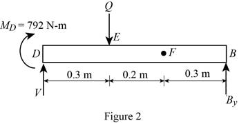
Determine the magnitude of the load Q by taking moment about the point D.
Show the free body diagram of the entire beam as in Figure 3.
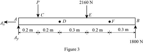
Determine the magnitude of the load P by taking moment about the point A.
Determine the vertical reaction at point A by resolving the vertical component of forces.
Shear force:
Show the calculation of shear force as follows;
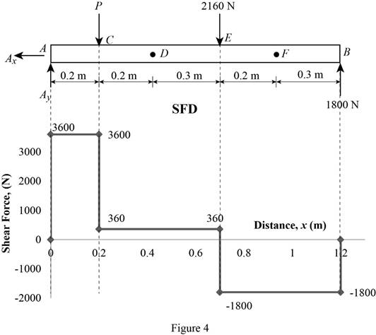
Show the calculated shear force values as in Table 1.
| Location (x) m | Shear force (V) N |
| A | 3600 |
| C (Left) | 3600 |
| C (Right) | 360 |
| E (Left) | 360 |
| E (Right) | –1800 |
| B | –1800 |
Plot the shear force diagram as in Figure 4.
Bending moment:
Show the calculation of the bending moment as follows;
Show the calculated bending moment values as in Table 2.
| Location (x) m | Bending moment (M) N-m |
| A | 0 |
| C | 720 |
| E | 900 |
| B | 0 |
Plot the bending moment diagram as in Figure 5.
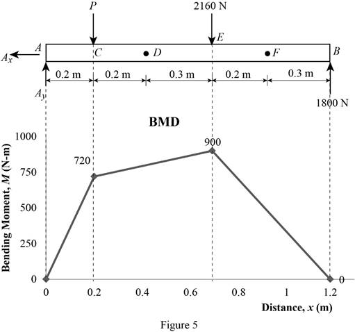
Refer to Figure 5;
The maximum absolute bending moment is
(b)
The maximum normal stress due to bending.
Answer to Problem 62P
The maximum normal stress due to bending is
Explanation of Solution
Given information:
Determine the section modulus (S) of the rectangular beam section using the equation.
Here, the width of the beam is b and the depth of the beam is h.
Substitute 24 mm for b and 60 mm for h.
The maximum absolute bending moment is
Determine the maximum normal stress
Substitute
Therefore, the maximum normal stress due to bending is
Want to see more full solutions like this?
Chapter 5 Solutions
Mechanics of Materials, 7th Edition


- A beam carries the loading shown in Fig. 4. Determine, (a) the smallest allowable width b of the beam if the maximum allowable bending stress is 93.75 MN/m². (b) to reduce the weight, a bore was made at the center of the rectangle with a diameter of 60 mm, what is the second moment of area of the resulting shape? 3 m 2 kN/m B www. 9 m Fig. 4 8 kN 3 m D 0000 1 160 mmarrow_forwardI need help solving Problem 5.30 5.29) Knowing that P = Q = 480 N, determine (a) the distance a for which the absolute value of the bending moment in the beam is as small as possible, (b) the corresponding maximum normal stress due to bending. (See hint of Prob. 5.27. 5.30) Solve Prob. 5.29, assuming that P = 480 N and Q = 320 N.arrow_forward5.7 For the cantilever beam shown in the figure, find (a) the maximum bending stress and its location; and (b) the bending stress at a point 20 mm from the top of the beam on section B. 1.0 kN/m 150 mm C A 2 m- 50 mm 6 m FIG. PS.7arrow_forward
- 0.6 m 25 kN/m 40 kN 1.8 m 40 KN C 0.6 m D PROBLEM 5.108 (a) Using singularity functions, write the equations for the shear and bending moment for the beam and loading shown. (b) Determine the maximum value of the bending moment in the beam.arrow_forward5.41 The inverted T-beam supports three concentrated loads as shown in the fig- ure. Find the maximum allowable value of Pif the bending stresses are not to exceed 3.5 ksi in tension and 8 ksi in compression. 14P 1.0 in. D 8 in. 1.0 in. 2 ft 3 ft 3 (t 2 tt - 4 int FIG. PS.41arrow_forwardd 5.23 Draw the shear and bending-moment diagrams for the beam and loading shown and determine the maximum normal stress due to bending. 80 kN/m 160 kN B C ID A E Hinge- W310 × 60 -2.4 m 1.5 m 1.5 m 0.6 marrow_forward
- Determine the bending stress in a 1-meter simple beam with a concentrated load of 1.25 kN at midspan. The beam has a rectangular section with b = 2 in and h = 4 in. а. 1.78 с. 3.58 b. 2.56 d. Answer is not among the choicesarrow_forwardPROBLEM 5.21 For the beam and loading shown, determine the maximum bending stress on a transverse section at C. [Ans. 10.89 MPa] 10 kN 3 kN/m 100 mm 25 de 200 mm B 1.5 m 1.5 m X-X 2.2 m splay E23 Fig. P5.21 Chp Show all 205 14 04/22 ALING • SPARKLING PURDEY'S NATURAL ENERGT REFOCUS Dark Fruits with guarana Paune hp Prien Sem Sysha Scroll Serril Lock F11 F10 F9 Num Lock F8 Page Up F7 F6 Home F5 bert F4 7 Page Down Home End Deletearrow_forwardPROBLEMS 5.16, 5.17 Draw the shear and bending- moment diagrams for the beam and loading shown, and determine the maximum absolute value (a) of the shear, and (b) of the bending moment. 68 kN 30 kN/m D -1.2 m 1.2 m 1.2 m- Fig. P5.16 PROBLEM 5.21 For the beam and loading shown, bending stress on a transverse sectiarrow_forward
- The rigid bar DEF is welded at point D to the steel beam AB. For the loading shown, determine (a) the equations defining the shear and bending at portion AD of the steel beam AB, (b) the location and magnitude of the largest bending moment. (Hint: Replace the 700 N load applied at F by an equivalent force-couple system at D) 750 N/m B D 000 E 2.4 m X 0.9 m 700 N -1.5 m.arrow_forward5.16 The box beam is made by nailing four 2-in. by 8-in. planks together as shown. (a) Show that the moment of inertia of the cross-sectional area about the neutral axis is 981.3 in.. (b) Given that wo 300 lb/ft, find the largest allowable force P if the bending stress is limited to 1400 psi. 8 in.2 in. 8 in. 9 f 3 ft 2 in. FIG. P5.16arrow_forwardProb. #2. An overhanging beam with a length of 12 ft. is fixed at the left end. It has a load of uniformly distributed load of 100 lb/ft located 4 ft fr. The left support and covers the remaining length of the beam. Draw completely the shear and bending moment for this beam.arrow_forward
 Elements Of ElectromagneticsMechanical EngineeringISBN:9780190698614Author:Sadiku, Matthew N. O.Publisher:Oxford University Press
 Mechanics of Materials (10th Edition)Mechanical EngineeringISBN:9780134319650Author:Russell C. HibbelerPublisher:PEARSON
 Thermodynamics: An Engineering ApproachMechanical EngineeringISBN:9781259822674Author:Yunus A. Cengel Dr., Michael A. BolesPublisher:McGraw-Hill Education
 Control Systems EngineeringMechanical EngineeringISBN:9781118170519Author:Norman S. NisePublisher:WILEY
 Mechanics of Materials (MindTap Course List)Mechanical EngineeringISBN:9781337093347Author:Barry J. Goodno, James M. GerePublisher:Cengage Learning
 Engineering Mechanics: StaticsMechanical EngineeringISBN:9781118807330Author:James L. Meriam, L. G. Kraige, J. N. BoltonPublisher:WILEY