
Concept explainers
Videos
The maximum normal stress due to bending on section a-a.
Answer to Problem 48P
The maximum normal stress due to bending on section a-a is
Explanation of Solution
Show the free-body diagram of the entire beam as in Figure 1.
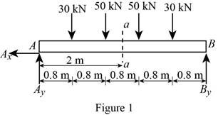
Determine the vertical reaction at point A by taking moment about point B.
Determine the vertical reaction at point B by resolving the vertical component of forces.
Determine the horizontal direction at point A by resolving the horizontal component of forces.
Shear force:
Show the calculation of shear force as follows;
Bending moment:
Show the calculation of bending moment as follows;
The bending moment at the section a-a is
Refer to Appendix C “Properties of Rolled-Steel Sections” in the textbook.
The section modulus for
Determine the maximum normal stress
Substitute
Therefore, the maximum normal stress due to bending on section a-a is
Want to see more full solutions like this?
Chapter 5 Solutions
Mechanics of Materials, 7th Edition


- P.16.4 A thin-walled cantilever with walls of constant thickness t has the cross- section shown in Fig. P.16.4. It is loaded by a vertical force W at the tip and a horizontal force 2W at the mid-section, both forces acting through the shear centre. Determine and sketch the distribution of direct stress, according to the basic theory of bending, along the length of the beam for the points 1 and 2 of the cross-section. The wall thickness t can be taken as very small in comparison with d in calculating the sectional properties Lxx, Ixy, etc. Ans. 2,1 (mid-point) = -0.05 Wl/td², 02,1 (built-in end) = -1.85 Wl/td² ₂2 (mid-point) = -0.63 W1/td², 02 (built-in end) = 0.1 Wl/td². /////// Fig. P.16.4 W 7/2 2W 1/2 A 2 d12_ _d12. 3 Xarrow_forwardA cable AB of span L and a simple beam A'B' of the same span are subjected to identical vertical loadings as shown. Show that the magnitude of the bending moment at a point C' in the beam is equal to the product T0h, where T0 is the magnitude of the horizontal component of the tension force in the cable and h is the vertical distance between point C and the chord joining the points of support A and B.arrow_forwardSolve Prob. 7.43 knowing that P= 3wa.(Reference to Problem 7.43):Assuming the upward reaction of the ground on beam AB to be uniformly distributed and knowing that P= wa, (a) draw the shear and bending-moment diagrams, (b) determine the maximum absolute values of the shear and bending moment.arrow_forward
- 5.19 and 5.20 For the beam and loading shown, determine the maxi- mum normal stress due to bending on a transverse section at C. 150 kN 150 kN 90 N/m W460 x 113 2.4 m 0.8 m 0.S m Fig. PS.20arrow_forwardProblem 1. For the beam and loading shown. a. Determine the distance x for which the maximum absolute value of the bending moment in the beam is as small as possible. b. Determine the maximum moment. c. Determine the maximum normal stress due to bending. 120 mm 500 kN 500 kN 500 mm 500 mm ! 180 mmarrow_forward0.6 m 25 kN/m 40 kN 1.8 m 40 KN C 0.6 m D PROBLEM 5.108 (a) Using singularity functions, write the equations for the shear and bending moment for the beam and loading shown. (b) Determine the maximum value of the bending moment in the beam.arrow_forward
- d 5.23 Draw the shear and bending-moment diagrams for the beam and loading shown and determine the maximum normal stress due to bending. 80 kN/m 160 kN B C ID A E Hinge- W310 × 60 -2.4 m 1.5 m 1.5 m 0.6 marrow_forward5.82 The simply supported wood beam, fabricated by gluing together fourwooden boards, carries the three concentrated forces. The working bending and shear stresses for the wood are 1000 psi and 600 psi, respectively. Determine the largest allowable value of the force P.arrow_forwardDetermine (a) the distance a for which the absolute value of the bending moment in the beam is as small as possible, (b) the corresponding moximum normal stress due to bending.arrow_forward
- (B) Q: The cantilever beam shown below has a circular cross section of 50mm outer diameter. Portion AB of the beam is hollow, with an inner diameter of 35mm. If the allowable bending stress is 140 MPa, determine (1) the largest allowable uniformly distributed load (w) that can be applied to the beam; (2) the bending stress at a point that is 7 mm below the top of the beam at section D. 50 mm W D B O! 35 mm A - 750 mm 250 mmarrow_forwardFig. P7.32 A W 2 B 2arrow_forwardL/4 D L/2 LA B A timber beam AB of length L and rectangular cross section carries a uniformly distributed load w and is supported as shown. (a) Show that the ratio of the maximum values of the shearing and normal stresses in the beam is equal to 2h/L, where h and L are, respectively, the depth and the length of the beam. (b) Determine the depth h and the width b of the beam, knowing that L = 5 m, w = 8 kN/m, Tm = 1.08 MPa, and om = 12 MPa.arrow_forward
 Elements Of ElectromagneticsMechanical EngineeringISBN:9780190698614Author:Sadiku, Matthew N. O.Publisher:Oxford University Press
 Mechanics of Materials (10th Edition)Mechanical EngineeringISBN:9780134319650Author:Russell C. HibbelerPublisher:PEARSON
 Thermodynamics: An Engineering ApproachMechanical EngineeringISBN:9781259822674Author:Yunus A. Cengel Dr., Michael A. BolesPublisher:McGraw-Hill Education
 Control Systems EngineeringMechanical EngineeringISBN:9781118170519Author:Norman S. NisePublisher:WILEY
 Mechanics of Materials (MindTap Course List)Mechanical EngineeringISBN:9781337093347Author:Barry J. Goodno, James M. GerePublisher:Cengage Learning
 Engineering Mechanics: StaticsMechanical EngineeringISBN:9781118807330Author:James L. Meriam, L. G. Kraige, J. N. BoltonPublisher:WILEY