
Applied Statics and Strength of Materials (6th Edition)
6th Edition
ISBN: 9780133840544
Author: George F. Limbrunner, Craig D'Allaird, Leonard Spiegel
Publisher: PEARSON
expand_more
expand_more
format_list_bulleted
Concept explainers
Videos
Textbook Question
Chapter 5, Problem 5.39SP
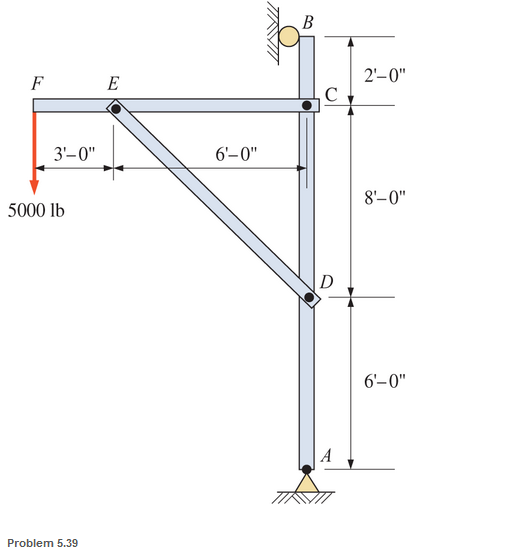
A pin-connected crane framework is loaded and supported, as shown. The member weights are post, 700 Ib; boom, 800 Ib; and brace, 600 Ib. These weights may be considered to be acting at the midpoint of the respective members Calculate the pin reactions at pins A. B. C. D. and E.
Expert Solution & Answer
Want to see the full answer?
Check out a sample textbook solution
Students have asked these similar questions
A simply supported truss is shown below. There is a pin support at A anda roller support at D. Determine the support reactions and the internalforce in each member. Use the method of joints
6. A truss which consists of a single, equilateral triangle, is supported by a pin and roller as
shown (an equilateral triangle has 3 equal, 60 degree internal angles). The truss is loaded
at point B by Dudley, sitting on a feeder, weighing a total of 520 Ibs (assume the truss
weight is negligible). What is the force in member AB? (Hint: Determine the horizontal
reaction at A first by summing moments about C - you will need to find the perpendicular
distance from C to the line of action of the force. Then use a FBD at A and equations of
equilibrium to determine the force in AB).
18 ft
Dudley
520 lbs PLATFORM
The T-bar AEBF is connected to rod CD, with the joint at F being equivalent to a slider bearing. The supports at A and C are slider bearings, and thrust bearings are found at B and D. The two applied forces, which act at the midpoint of the arm EF, are parallel to the y- and z-axes, respectively. Neglecting the weights of the members, draw the FBDs for the entire structure, the T-bar, and rod CD. Determine the total number of unknowns.
Chapter 5 Solutions
Applied Statics and Strength of Materials (6th Edition)
Ch. 5 - through 5.7 Calculate the forces in all members of...Ch. 5 - Calculate the forces in all members of the trusses...Ch. 5 - Calculate the forces in all members of the trusses...Ch. 5 - Calculate the forces in all members of the trusses...Ch. 5 - Calculate the forces in all members of the trusses...Ch. 5 - Calculate the forces in all members of the trusses...Ch. 5 - Calculate the forces in all members of the trusses...Ch. 5 - Determine the forces in members CD, DH, and HI for...Ch. 5 - Determine the forces in members BC, BE, and FE for...Ch. 5 - Determine the forces in members BC, CH, and CG in...
Ch. 5 - For the Howe roof truss shown, determine the...Ch. 5 - Determine the forces in members DE, CE, and BC in...Ch. 5 - Calculate the forces in members BC, BG, and FG for...Ch. 5 - Determine the forces in members CD, BD, BE, and CB...Ch. 5 - A pin-connected A-frame supports a load, as shown....Ch. 5 - Determine the pin reactions at pins A, B, and C in...Ch. 5 - Calculate the pin reactions at each of the pins in...Ch. 5 - A bracket is pin connected at points A, B, and D...Ch. 5 - A pin-connected frame is loaded, as shown....Ch. 5 - The cylinder shown has a mass of 500 kg. Determine...Ch. 5 - A simple frame is pin connected at points A, B,...Ch. 5 - Using the method of sections, determine the forces...Ch. 5 - Using the method of sections, determine the forces...Ch. 5 - through 5.31 Calculate the forces in all members...Ch. 5 - Calculate the forces in all members of the trusses...Ch. 5 - Calculate the forces in all members of the trusses...Ch. 5 - Calculate the forces in all members of the trusses...Ch. 5 - Calculate the forces in all members of the trusses...Ch. 5 - Calculate the forces in all members of the trusses...Ch. 5 - Calculate the forces in all members of the trusses...Ch. 5 - Calculate the forces in all members of the trusses...Ch. 5 - For Problems 5.32 through 5.38, calculate the...Ch. 5 - For Problem 5.32 through 5.38, Calculate the...Ch. 5 - For Problems 5.32 through 5.38, calculate the...Ch. 5 - For Problems 5.32 through 5.38, calculate the...Ch. 5 - For Problem 5.32 through 5.38 , Calculate the...Ch. 5 - For Problems 5.32 through 5.38, calculate the...Ch. 5 - For Problems 5.32 through 5.38, calculate the...Ch. 5 - A pin-connected crane framework is loaded and...Ch. 5 - Calculate the pin reactions at pins A, B, and D in...Ch. 5 - Determine the pin reactions at pins A, B, and C in...Ch. 5 - The wall bracket shown is pin-connected at points...Ch. 5 - Calculate the pin reactions at each of the pins in...Ch. 5 - The A-frame shown is pin-connected at A,B,C, and...Ch. 5 - The tongs shown are used to grip an object. For an...Ch. 5 - A toggle joint is a mechanism by which a...Ch. 5 - In the toggle joint of Problem 5.46 , assume that...Ch. 5 -
Knowledge Booster


Learn more about
Need a deep-dive on the concept behind this application? Look no further. Learn more about this topic, mechanical-engineering and related others by exploring similar questions and additional content below.Similar questions
- The frame shown is loaded by a 180-1b force applied to member AE. Determine the force at pin A, the reaction at support B, and the contact force at roller C. Note that there is no friction at rollers C and D. 180 lb 4 in. in. 4 in. 4 in. 2 in. 2 in.arrow_forwardA pin-connected system of bars supports a 300-lb load as shown in Fig. ports A and B and the force exerted by the pin at Con mem- her ACE Determine the reactions at sup- 20 in. 300 lb -10 in. 10 in. -10 in.arrow_forwardThe structure shown below is a simplified tower crane. It carries a shipping crate suspended from B that has a weight of 116 kN . The main jib DCB (in green) has a weight of 17 kN concentrated in the center of the beam. This is pinned to the main body at D and is supported by a cable that is routed through pulleys at F and G and is attached to a concrete counterweight J. The main body AEFG (in yellow) is fixed to the ground at A. Various geometry: h1= 26.5 m h2= 3.9 m h3= 5.1 m l1= 12.8 m l2= 17 m l3= 4.3 mm θ= 57.6 degrees Assumptions : The main body AEFG can be considered massless. The cable CFGJ is massless. The pulleys at F and G can be considered massless, frictionless, and of negligible diameter. All bodies are considered rigid. Questions: Determine the x−component of the reaction force at fixed support A, otherwise known as Ax Determine the y−component of the reaction force at fixed support A, otherwise known as Ay. Determine the reaction moment at fixed support A,…arrow_forward
- A pin-connected crane framework is loaded and supported, as shown. The member weights are post, 700 lb; boom, 800 lb; and brace, 600 lb. These weights may be considered to be acting at the midpoint of the respective members. Calculate the pin reactions at pins A, C, D, E and at the roller B - Draw Free-body diagram. - Solve most simpliest way, only solving for what you are asked for.arrow_forwardThe given structure was supported by pin supports at points D and E. Member EF, DFG and BGC are connected to each other by internal hinges at B and F and a slider at G. (The slider at G allows relative horizontal motions of members BGC and DFG but constrains the vertical movement of members BGC and DFG. Calculate the support reactions due to pin supports and all internal hinge reactions. Show your calculation steps in detail and write your answers in the box below. E 1 m 3 kN/m B G 1 m F A -t-1 m-|-1 m--1 m- 2 m Darrow_forwardThe structure shown below is a simplified tower crane. It carries a shipping crate suspended from B that has a weight of 116 kN . The main jib DCB (in green) has a weight of 17 kN concentrated in the center of the beam. This is pinned to the main body at D and is supported by a cable that is routed through pulleys at F and G and is attached to a concrete counterweight J. The main body AEFG (in yellow) is fixed to the ground at A. Various geometry: h1= 26.5 m h2= 3.9 m h3= 5.1 m l1= 12.8 m l2= 17 m l3= 4.3 mm θ= 57.6 degrees Assumptions : The main body AEFG can be considered massless. The cable CFGJ is massless. The pulleys at F and G can be considered massless, frictionless, and of negligible diameter. All bodies are considered rigid. Questions: Determine the weight of counterweight J in order for the main jib DCB to be horizontal. Determine the magnitude of the x and y components of force at pin D. Determine the reactions at fixed support A.arrow_forward
- Q: Find the force in members AC and BC of the Truss shown below?arrow_forwardThe frame shown is loaded by a 180-1b force applied to member AE. Determine the force at pin A, the reaction at support B, and the contact force at roller C. Note that there is no friction at rollers C and D. E 180 lb 4 in. 2 in. Value (left, right, upward/downward Reaction 4 in. 4 in. 2 in. 2 in. A BX BY Darrow_forwardThe truss carries the loads as shown in Figure 2. The truss is supported by pin at A and smoothroller support at G. (b)By using method of section, determine the force in members CD, CJ and KJ of the truss.State if the members are in tension or compression.arrow_forward
- Problem 6. The truss below was designed to hang a one-of-a-kind sign that weighs 1000 lb. The sign is attached to the truss by two cables at attached at pin H of the truss and a rod that is attached at pin G of the truss; the rod is pin connected at both ends. The truss is attached to the wall by a pin at A and another cable (there are 3 cables at point H). Find the internal force in members AE, CH, EC, and EF. H cable cable 8' pin B с cable 8' 3' 3' rod E F 6' 1' 1.5' 2'> sign: 6'x 8', 1000 lbarrow_forwardFor the truss loaded and supported as shown in figure, determine the forces in member CD, DG and GH using method of sections.arrow_forwardFind the forces in members EF, KL, and GL for the Fink truss shown. Answer using method of section.arrow_forward
arrow_back_ios
SEE MORE QUESTIONS
arrow_forward_ios
Recommended textbooks for you
 International Edition---engineering Mechanics: St...Mechanical EngineeringISBN:9781305501607Author:Andrew Pytel And Jaan KiusalaasPublisher:CENGAGE L
International Edition---engineering Mechanics: St...
Mechanical Engineering
ISBN:9781305501607
Author:Andrew Pytel And Jaan Kiusalaas
Publisher:CENGAGE L
Types Of loads - Engineering Mechanics | Abhishek Explained; Author: Prime Course;https://www.youtube.com/watch?v=4JVoL9wb5yM;License: Standard YouTube License, CC-BY