
Applied Statics and Strength of Materials (6th Edition)
6th Edition
ISBN: 9780133840544
Author: George F. Limbrunner, Craig D'Allaird, Leonard Spiegel
Publisher: PEARSON
expand_more
expand_more
format_list_bulleted
Concept explainers
Videos
Textbook Question
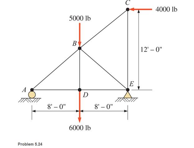
Chapter 5, Problem 5.24SP
through 5.31 Calculate the forces in all members of the trusses shown, using the method of joints.
Expert Solution & Answer

Learn your wayIncludes step-by-step video

schedule14:14
Students have asked these similar questions
A truss of span 10 meters is loaded as shown in the figure. Find the forces in all the members of the truss using method of joints and method of sections.
Using the method of joints, calculate the force in each member of the truss shown. State whether each member is in tension or compression.
For the next Trusses, compute the axial forces in the selected sections. Compare the result with the method of joints.
(Check the image for the trusses)
Chapter 5 Solutions
Applied Statics and Strength of Materials (6th Edition)
Ch. 5 - through 5.7 Calculate the forces in all members of...Ch. 5 - Calculate the forces in all members of the trusses...Ch. 5 - Calculate the forces in all members of the trusses...Ch. 5 - Calculate the forces in all members of the trusses...Ch. 5 - Calculate the forces in all members of the trusses...Ch. 5 - Calculate the forces in all members of the trusses...Ch. 5 - Calculate the forces in all members of the trusses...Ch. 5 - Determine the forces in members CD, DH, and HI for...Ch. 5 - Determine the forces in members BC, BE, and FE for...Ch. 5 - Determine the forces in members BC, CH, and CG in...
Ch. 5 - For the Howe roof truss shown, determine the...Ch. 5 - Determine the forces in members DE, CE, and BC in...Ch. 5 - Calculate the forces in members BC, BG, and FG for...Ch. 5 - Determine the forces in members CD, BD, BE, and CB...Ch. 5 - A pin-connected A-frame supports a load, as shown....Ch. 5 - Determine the pin reactions at pins A, B, and C in...Ch. 5 - Calculate the pin reactions at each of the pins in...Ch. 5 - A bracket is pin connected at points A, B, and D...Ch. 5 - A pin-connected frame is loaded, as shown....Ch. 5 - The cylinder shown has a mass of 500 kg. Determine...Ch. 5 - A simple frame is pin connected at points A, B,...Ch. 5 - Using the method of sections, determine the forces...Ch. 5 - Using the method of sections, determine the forces...Ch. 5 - through 5.31 Calculate the forces in all members...Ch. 5 - Calculate the forces in all members of the trusses...Ch. 5 - Calculate the forces in all members of the trusses...Ch. 5 - Calculate the forces in all members of the trusses...Ch. 5 - Calculate the forces in all members of the trusses...Ch. 5 - Calculate the forces in all members of the trusses...Ch. 5 - Calculate the forces in all members of the trusses...Ch. 5 - Calculate the forces in all members of the trusses...Ch. 5 - For Problems 5.32 through 5.38, calculate the...Ch. 5 - For Problem 5.32 through 5.38, Calculate the...Ch. 5 - For Problems 5.32 through 5.38, calculate the...Ch. 5 - For Problems 5.32 through 5.38, calculate the...Ch. 5 - For Problem 5.32 through 5.38 , Calculate the...Ch. 5 - For Problems 5.32 through 5.38, calculate the...Ch. 5 - For Problems 5.32 through 5.38, calculate the...Ch. 5 - A pin-connected crane framework is loaded and...Ch. 5 - Calculate the pin reactions at pins A, B, and D in...Ch. 5 - Determine the pin reactions at pins A, B, and C in...Ch. 5 - The wall bracket shown is pin-connected at points...Ch. 5 - Calculate the pin reactions at each of the pins in...Ch. 5 - The A-frame shown is pin-connected at A,B,C, and...Ch. 5 - The tongs shown are used to grip an object. For an...Ch. 5 - A toggle joint is a mechanism by which a...Ch. 5 - In the toggle joint of Problem 5.46 , assume that...Ch. 5 -
Additional Engineering Textbook Solutions
Find more solutions based on key concepts
The data shown in the following graph was collected during testing of an electromagnetic mass driver. The energ...
Thinking Like an Engineer: An Active Learning Approach (3rd Edition)
1.1 Convert 1250 millimeters to meters.
Applied Fluid Mechanics (7th Edition)
State if these members are in tension or compression. Probs. 6-32
Engineering Mechanics: Statics
The moment of force about point O.
Engineering Mechanics: Statics & Dynamics (14th Edition)
If crank OA rotates with an angular velocity of = 12 rid/s, determine the velocity of piston B and the angular...
Engineering Mechanics: Dynamics (14th Edition)
Determine the tension in the cables in order to support the 100-kg crate in the equilibrium position shown.
INTERNATIONAL EDITION---Engineering Mechanics: Statics, 14th edition (SI unit)
Knowledge Booster


Learn more about
Need a deep-dive on the concept behind this application? Look no further. Learn more about this topic, mechanical-engineering and related others by exploring similar questions and additional content below.Similar questions
- Problem 5.2 Calculate the forces in all members of the trusses shown using the method of joints. Please show all work and units. Thanksarrow_forwardCalculate the forces in all members of the trusses shown using the method of joints.arrow_forwardFor the truss shown below and using the method of joints, find the forces acting along segment AB, and ACarrow_forward
- A truss of span 10 meters is loaded as shown in the figure. Find the forces in all the members of the truss using method of sections.arrow_forwardFor the frame shown below, Calculate the support reactions at A and C Calculate the internal force at Darrow_forwardUsing the method of joints, calculate the force in each member of the trusse shown. State whether each member is in tension or compression.arrow_forward
- For truss shown in figure, determine the value of the forces in members AB and HB if P is 10 kNarrow_forwardUsing the method of joints, calculate the force in each memberof the trusses shown. State whether each member is in tension or compression.arrow_forwardFor the truss shown, Calculate the reactions at the supports Calculate all member forces using the method of joints. Hint: Start at joint Darrow_forward
- Looking at the figure assume the truss is pin supported on both ends. Calculate the axial forces in members: AB, BC, BD, and BE.arrow_forwardQ: Find the force in members AC and BC of the Truss shown below?arrow_forwardA cantilever truss has been as shown in the figure. Find the value of W which will produces a force of magnitudes 15 kN in the member AB.arrow_forward
arrow_back_ios
SEE MORE QUESTIONS
arrow_forward_ios
Recommended textbooks for you
 Elements Of ElectromagneticsMechanical EngineeringISBN:9780190698614Author:Sadiku, Matthew N. O.Publisher:Oxford University Press
 Mechanics of Materials (10th Edition)Mechanical EngineeringISBN:9780134319650Author:Russell C. HibbelerPublisher:PEARSON
 Thermodynamics: An Engineering ApproachMechanical EngineeringISBN:9781259822674Author:Yunus A. Cengel Dr., Michael A. BolesPublisher:McGraw-Hill Education
 Control Systems EngineeringMechanical EngineeringISBN:9781118170519Author:Norman S. NisePublisher:WILEY
 Mechanics of Materials (MindTap Course List)Mechanical EngineeringISBN:9781337093347Author:Barry J. Goodno, James M. GerePublisher:Cengage Learning
 Engineering Mechanics: StaticsMechanical EngineeringISBN:9781118807330Author:James L. Meriam, L. G. Kraige, J. N. BoltonPublisher:WILEY
Elements Of Electromagnetics
Mechanical Engineering
ISBN:9780190698614
Author:Sadiku, Matthew N. O.
Publisher:Oxford University Press
Mechanics of Materials (10th Edition)
Mechanical Engineering
ISBN:9780134319650
Author:Russell C. Hibbeler
Publisher:PEARSON
Thermodynamics: An Engineering Approach
Mechanical Engineering
ISBN:9781259822674
Author:Yunus A. Cengel Dr., Michael A. Boles
Publisher:McGraw-Hill Education
Control Systems Engineering
Mechanical Engineering
ISBN:9781118170519
Author:Norman S. Nise
Publisher:WILEY
Mechanics of Materials (MindTap Course List)
Mechanical Engineering
ISBN:9781337093347
Author:Barry J. Goodno, James M. Gere
Publisher:Cengage Learning
Engineering Mechanics: Statics
Mechanical Engineering
ISBN:9781118807330
Author:James L. Meriam, L. G. Kraige, J. N. Bolton
Publisher:WILEY
Engineering Basics - Statics & Forces in Equilibrium; Author: Solid Solutions - Professional Design Solutions;https://www.youtube.com/watch?v=dQBvQ2hJZFg;License: Standard YouTube License, CC-BY