
Power System Analysis and Design (MindTap Course List)
6th Edition
ISBN: 9781305632134
Author: J. Duncan Glover, Thomas Overbye, Mulukutla S. Sarma
Publisher: Cengage Learning
expand_more
expand_more
format_list_bulleted
Concept explainers
Videos
Textbook Question
Chapter 2, Problem 2.31P
Consider two interconnected voltage sources connected by a line of impedance
(a) Obtain expressions for
(b) Determine the maximum power transfer and the condition for it to 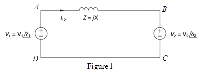
Expert Solution & Answer

Trending nowThis is a popular solution!

Students have asked these similar questions
Q.3
(a) The short circuit MVA at the terminal of generating Station A and B are 1100
MVA and 1200 MVA respectively. The generated voltage at each station is 33
kV. If these stations are interconnected through a line having a reactance of 1.5 2
and negligible resistance, calculate the possible short-circuit MVA at both station.
Choose 100 MVA as base.
(b) A power system is represented by one line diagram in Figure Q.3(b). Each bus is
rated at line voltage of 66 kV.
The reactance of each component is given in per unit, based 100 MVA and rated
voltage of the component. Assume that the prefault voltage of each generator is
to be 1.0 per unit.
Bus impedance matrix with all elements in per unit for the system is given below:
j0.138 j0.112 j0.130
j0.138 j0.121
Zj0.112
jo.130 j0.121 j0.160
A solid three phase fault occurs at bus 1. Determine:
(i)
Fault current (in Ampere) and fault level (in MVA) at Bus 1.
(ii) Transmission lines current (in Ampere) during fault.
If line L23 is connected in…
c) A heater with resistance 10 N is driven by an AC voltage source (120 V). For the circuit shown
below, determine the following:
0.50
j5n
Vs
120 V/50 Hz
j1n
Figure Ql
i. The total circuit impedance, Zr, in polar form.
11. The supply current, I..
iiI. The phasor diagram indicating the supply voltage, V, and the supply current,
17
iv. Apparent Power, Real Power, Reactive Power and Power Factor.
V. The heater output power.
100
Impedances Z2 and Z3 in parallel are in series with impedance Z1 across a 100 V, 50 Hz ac supply. Z1 =6.25 + j1.25 ohm; Z2 = 5+ j0 ohm and Z3 = 5-jXc ohm. Determine the value of capacitance of Xc such that the total curent of the circuit will be in phase with the total voltage. When is then the circuit current and power.
Chapter 2 Solutions
Power System Analysis and Design (MindTap Course List)
Ch. 2 - The rms value of v(t)=Vmaxcos(t+) is given by a....Ch. 2 - If the rms phasor of a voltage is given by V=12060...Ch. 2 - If a phasor representation of a current is given...Ch. 2 - Prob. 2.4MCQCh. 2 - Prob. 2.5MCQCh. 2 - Prob. 2.6MCQCh. 2 - Prob. 2.7MCQCh. 2 - Prob. 2.8MCQCh. 2 - Prob. 2.9MCQCh. 2 - The average value of a double-frequency sinusoid,...
Ch. 2 - The power factor for an inductive circuit (R-L...Ch. 2 - The power factor for a capacitive circuit (R-C...Ch. 2 - Prob. 2.13MCQCh. 2 - The instantaneous power absorbed by the load in a...Ch. 2 - Prob. 2.15MCQCh. 2 - With generator conyention, where the current...Ch. 2 - Consider the load convention that is used for the...Ch. 2 - Prob. 2.18MCQCh. 2 - The admittance of the impedance j12 is given by...Ch. 2 - Consider Figure 2.9 of the text, Let the nodal...Ch. 2 - The three-phase source line-to-neutral voltages...Ch. 2 - In a balanced three-phase Y-connected system with...Ch. 2 - In a balanced system, the phasor sum of the...Ch. 2 - Consider a three-phase Y-connected source feeding...Ch. 2 - For a balanced- load supplied by a balanced...Ch. 2 - A balanced -load can be converted to an...Ch. 2 - When working with balanced three-phase circuits,...Ch. 2 - The total instantaneous power delivered by a...Ch. 2 - The total instantaneous power absorbed by a...Ch. 2 - Under balanced operating conditions, consider the...Ch. 2 - One advantage of balanced three-phase systems over...Ch. 2 - While the instantaneous electric power delivered...Ch. 2 - Given the complex numbers A1=630 and A2=4+j5, (a)...Ch. 2 - Convert the following instantaneous currents to...Ch. 2 - The instantaneous voltage across a circuit element...Ch. 2 - For the single-phase circuit shown in Figure...Ch. 2 - A 60Hz, single-phase source with V=27730 volts is...Ch. 2 - (a) Transform v(t)=75cos(377t15) to phasor form....Ch. 2 - Let a 100V sinusoidal source be connected to a...Ch. 2 - Consider the circuit shown in Figure 2.23 in time...Ch. 2 - For the circuit shown in Figure 2.24, compute the...Ch. 2 - For the circuit element of Problem 2.3, calculate...Ch. 2 - Prob. 2.11PCh. 2 - The voltage v(t)=359.3cos(t)volts is applied to a...Ch. 2 - Prob. 2.13PCh. 2 - A single-phase source is applied to a...Ch. 2 - Let a voltage source v(t)=4cos(t+60) be connected...Ch. 2 - A single-phase, 120V(rms),60Hz source supplies...Ch. 2 - Consider a load impedance of Z=jwL connected to a...Ch. 2 - Let a series RLC network be connected to a source...Ch. 2 - Consider a single-phase load with an applied...Ch. 2 - A circuit consists of two impedances, Z1=2030 and...Ch. 2 - An industrial plant consisting primarily of...Ch. 2 - The real power delivered by a source to two...Ch. 2 - A single-phase source has a terminal voltage...Ch. 2 - A source supplies power to the following three...Ch. 2 - Consider the series RLC circuit of Problem 2.7 and...Ch. 2 - A small manufacturing plant is located 2 km down a...Ch. 2 - An industrial load consisting of a bank of...Ch. 2 - Three loads are connected in parallel across a...Ch. 2 - Prob. 2.29PCh. 2 - Figure 2.26 shows three loads connected in...Ch. 2 - Consider two interconnected voltage sources...Ch. 2 - Prob. 2.35PCh. 2 - Prob. 2.36PCh. 2 - Prob. 2.37PCh. 2 - Prob. 2.38PCh. 2 - Prob. 2.39PCh. 2 - A balanced three-phase 240-V source supplies a...Ch. 2 - Prob. 2.41PCh. 2 - A balanced -connected impedance load with (12+j9)...Ch. 2 - A three-phase line, which has an impedance of...Ch. 2 - Two balanced three-phase loads that are connected...Ch. 2 - Two balanced Y-connected loads, one drawing 10 kW...Ch. 2 - Three identical impedances Z=3030 are connected in...Ch. 2 - Two three-phase generators supply a three-phase...Ch. 2 - Prob. 2.48PCh. 2 - Figure 2.33 gives the general -Y transformation....Ch. 2 - Consider the balanced three-phase system shown in...Ch. 2 - A three-phase line with an impedance of...Ch. 2 - A balanced three-phase load is connected to a...Ch. 2 - What is a microgrid?Ch. 2 - What are the benefits of microgrids?Ch. 2 - Prob. CCSQCh. 2 - Prob. DCSQ
Knowledge Booster


Learn more about
Need a deep-dive on the concept behind this application? Look no further. Learn more about this topic, electrical-engineering and related others by exploring similar questions and additional content below.Similar questions
- For the single-phase circuit shown in Figure 2.22, I5 10/08A. (a) Compute the phasors I1, I2, and V. (b) Draw a phasor diagram showing I, I1 I2, and Varrow_forwardQ3 (a) Given a circuit in Figure Q3(a); Determine the load impedance, Zı that results in maximum average power transferred to ZL. (i) (ii) Find the maximum average power transferred to the load impedance. jl 2 1220° V ZL -jl 2 Figure Q3(a)arrow_forwardObjective 3 ) -Be able to calculate all forms of ac power in ac circuits with linear transformers and ideal transformersarrow_forward
- ZL impedance for maximum average power transfer in the circuit shown in Figure 2and find the value of the maximum average power transferred to the ZL? (Can you write the steps in detail in sentences?)arrow_forward1. -) A sinusoidal voltage source in placed in series with a DC voltage source and produces an output of: v(t) = 70.7cos (377t) + 20 volts [ 70.7 = 50√2] Calculate: a. v²(t) b. Vrms C. The magnitude of the RMS current if the combined source is placed across a load of Z=4+j3 ohms (if you have trouble with part b, just assume a voltage of 100 Vrms for part c)arrow_forwardThree loads are connected in parallel across a 1400-V rms, 60-Hz single-phase supply as shown in Figure 2.8. Load 1: Inductive load, 125 kVA at 0.28 power factor. Load 2: Capacitive load, 10 kW and 40 kvar. Load 3: Resistive load of 15 kW. 1400 V (a) Find the total kW, kvar, kVA, and the supply power factor. 1 12 (b) A capacitor of negligible resistance is connected in parallel with the above loads to improve the power factor to 0.8 lagging. Determine the kvar rating of this ca- pacitor and the capacitance in uF. 13 3arrow_forward
- A d.c. serier generator, having an external characteristic which is a straight line through zero to 50 V 200 A is connected as a booster between a station bus bar and a feeder of 0.3 ohm resistane. Calculate the voltage difference between the station bus-bar and the far end of the feeder qa current of (i) 200 A and (ii) 50 A.arrow_forward1a)Analyze the circuit in Figure 1, consider R = 10 kQ and C = 10 nF. Obtain the mathematical equation for the equivalent impedance seen by the generator as a function of frequency. By voltage division obtain the mathematical relationship for the voltage across the capacitor and resistor as a function of VF and frequency. Perform all the circuit analysis (voltages, impedances, currents, waveforms). 1b) For the conditions in the previous item, deduce the value of the frequency that satisfies |XC| = R. Vf f=4 kHz R=1 kΩ C=10 nF Figure 1. Measurement circuit #1. Y X ORCarrow_forwardIn the circuit given in Figure 2, v,(t) = /2 · 50 cos(4t + 60°)V a) Find the equivalent load impedance. State whether the load is inductive or capacitive. b) Calculate the load current Ijoad. Write an expression for itoad(t). c) Calculate the load voltage Vload Write an expression for vioad(t). d) Calculate the active, reactive and apparent power of the load. Determine the power factor. 3.5 (N) i joa(1) + 70 (mF) v, (1) Vload (t) 14(2) 7(H) LOADarrow_forward
- Using Figure 1, Vs 50V-15 339 Hz R1 $1100 R2 100 www XL1 320 HH XC1 Figure 1 700 R3 600 13 R4 400 XL2 1902 XL3 450 XC2 650 a. Determine the total circuit impedance, ZT. b. Calculate current IT. c. Calculate currents I, and I3. State the value of these currents in both rectangular and polar form. d. For each of the currents determined in part c, answer the following: Is the current leading, lagging, or in phase with the source voltage. e. Use the voltage-divider rule to determine the voltages across XL1 and Xc2.arrow_forwardQ2. A series of motor (Load 1) and lighting (load 2) are connected to an AC source as shown in Figure Q2. The AC source, Vs, supplies 415420° V with frequency 50 Hz. Based on this information: 5Ω 100 mH 15Ω Load 1 Load 2 i) Calculate the total load impedance. 2) Vs ii) Calculate the current, I. Figure Q2. (iii) Write the waveform expressions in frequency domain for Vs and I. Draw a phasor diagram consists of Vs and I and state the relationship between Vs and I. Determine the power factor and calculate the real power, reactive power and apparent power. Establish the power triangle for the load. (iv)arrow_forwardConsider the circuit shown in Figure 2 below.a) Compute the phasor form of the load ZL that will absorb a maximum amount ofpower, and compute the maximum power delivered to this load. b) Show that the power delivered to the load is reduced if the load is ZL + j5.Explain why this is the case.arrow_forward
arrow_back_ios
SEE MORE QUESTIONS
arrow_forward_ios
Recommended textbooks for you
 Power System Analysis and Design (MindTap Course ...Electrical EngineeringISBN:9781305632134Author:J. Duncan Glover, Thomas Overbye, Mulukutla S. SarmaPublisher:Cengage Learning
Power System Analysis and Design (MindTap Course ...
Electrical Engineering
ISBN:9781305632134
Author:J. Duncan Glover, Thomas Overbye, Mulukutla S. Sarma
Publisher:Cengage Learning
Maximum Power Transfer Theorem Using Nodal Analysis & Thevenin Equivalent Circuits; Author: The Organic Chemistry Tutor;https://www.youtube.com/watch?v=8CA6ZNXgI-Y;License: Standard Youtube License