
Applied Statics and Strength of Materials (6th Edition)
6th Edition
ISBN: 9780133840544
Author: George F. Limbrunner, Craig D'Allaird, Leonard Spiegel
Publisher: PEARSON
expand_more
expand_more
format_list_bulleted
Concept explainers
Videos
Textbook Question
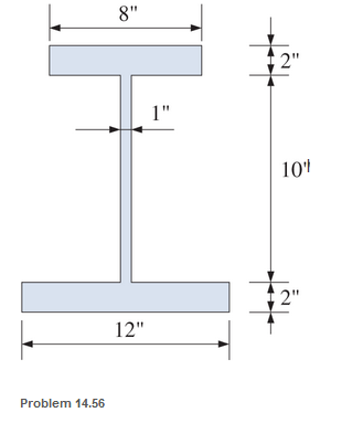
Chapter 14, Problem 14.56SP
Calculate the values of S and Z and the shape factor for the cross section shown.
Expert Solution & Answer
Want to see the full answer?
Check out a sample textbook solution
Students have asked these similar questions
Determine the location of the shear center for the beams having the cross-sectional dimensions shown in the figures. All members are to be considered thin walled, and calculations should be based on the centerline dimensions.
Expected solution for 10-41 and 10-42 is provided. please provide step by step solution.
Find the maximum shear force (V), the cross
section can carry if the maximum shear
stress is not to exceed 100MPa. And then
after calculating the value of V, FIND the
force carried by the web.
200 mm
20mm
20mm
V
210mm
20mm
110mm
Where is the centroid of the cross-section with respect to the bottom in mm?
In reference to Item 1, calculate for the moment of inertia with respect to the neutral axis in mm4.
In reference to Item 1, determine the maximum tension bending stresses produced in segment BC of the beam in MPa.
In reference to Item 1, determine the maximum compression bending stresses produced in segment BC of the beam in MPa.
Chapter 14 Solutions
Applied Statics and Strength of Materials (6th Edition)
Ch. 14 - Calculate the section modulus for: (a) a 6 -in-by-...Ch. 14 - Calculate the section modulus (with respect to the...Ch. 14 - Prob. 14.3PCh. 14 - Rework Problem 14.3 changing the orientation of...Ch. 14 - Assume that the timber member (a) of Problem 14.2...Ch. 14 - The structural steel built-up member (b) of...Ch. 14 - A round steel rod, 25 mm in diameter, is subjected...Ch. 14 - A square steel bar, 38 mm on each side, is used as...Ch. 14 - Calculate the moment strength for a W36302...Ch. 14 - Calculate the allowable bending moment for a solid...
Ch. 14 - The beams of cross sections shown are subjected to...Ch. 14 - A solid rectangular simply supported timber beam 6...Ch. 14 - A W1430 supports the loads shown. Calculate the...Ch. 14 - If the allowable shear stress is 100 MPa,...Ch. 14 - A steel pin 112 in diameter is subjected to a...Ch. 14 - A timber power-line pole is 10 in. in diameter at...Ch. 14 - Calculate the value of S and Z and the shape...Ch. 14 - For beams that have cross sections as shown for...Ch. 14 - Calculate the maximum load P that the beam shown...Ch. 14 - A 412 (S4S) hem-fir timber beam carries a...Ch. 14 - A simply supported W1636 A992 steel beam carries a...Ch. 14 - A W250115 steel wide-flange section supports a...Ch. 14 - Assume that the floor joist dimensions of Example...Ch. 14 - Calculate the allowable superimposed uniformly...Ch. 14 - A 3 -in.-by- 12 -in. (S4S) scaffold timber plank...Ch. 14 - For the following computer problems, any...Ch. 14 - For the following computer problems, any...Ch. 14 - For the following computer problems, any...Ch. 14 - Calculate the section modulus with respect to the...Ch. 14 - The timber box section (a) of Problem 14.29 is...Ch. 14 - A timber beam is subjected to a maximum bending...Ch. 14 - Rework Problem 14.31 assuming that the beam is...Ch. 14 - A 12 -in.-diameter steel rod projects 2 ft...Ch. 14 - Calculate the maximum bending stress in a W530101...Ch. 14 - A cantilever cast-iron beam is 6 ft long and has a...Ch. 14 - 14.36 Calculate the moment strength for a...Ch. 14 - A W813 steel wide-flange beam on a 20 -ft span is...Ch. 14 - A simply supported beam with a cruciform cross...Ch. 14 - A rectangular beam 100 mm in width and 250 mm in...Ch. 14 - The timber box section (a) of Problem 14.29 is...Ch. 14 - For the I-shaped timber beam shown, calculate the...Ch. 14 - 14.42 A steel wide-flange beam is oriented so that...Ch. 14 - A W1045steel wide-flange beam supports a uniformly...Ch. 14 - 14.44 A steel wide-flange section is subjected to...Ch. 14 - A W30108 steel wide-flange beam is simply...Ch. 14 - A W612 is strengthened with a 34 -in.-by- 34 -in....Ch. 14 - Four wood boards 1 in. by 6 in. in cross section...Ch. 14 - A lintel consists of two 8 -in.-by- 12 in. steel...Ch. 14 - A 50 -mm-by- 300 -mm scaffold timber plank, placed...Ch. 14 - A laminated wood beam is built up by gluing...Ch. 14 - A rectangular hollow shape carries loads as shown....Ch. 14 - For the beam shown, calculate the maximum tensile...Ch. 14 - 14.53 A box beam is built up of four -in.-by--in....Ch. 14 - 14.54 Find the value of the loads P that can be...Ch. 14 - 14.55 Solve Problem 14.54 assuming that the timber...Ch. 14 - Calculate the values of S and Z and the shape...Ch. 14 - 14.57 A is supported on simple supports on a -ft...
Knowledge Booster


Learn more about
Need a deep-dive on the concept behind this application? Look no further. Learn more about this topic, mechanical-engineering and related others by exploring similar questions and additional content below.Similar questions
- Determine the shape factor f for a cross section in the shape of a double trapezoid having the dimensions shown in the figure. Also, check your result for the special cases of a rhombus (b1= 0) and a rectangle (b1= b2).arrow_forwardA U-shaped cross section of constant thickness is shown in the figure. Derive the following formula for the distance e from the center of the semicircle to the shear center. Also, plot a graph showing how the distance e (expressed as the non dimensional ratio e/r varies as a function of the ratio b/r. (Let b/r range from 0 to 2.)arrow_forwardA cross section in the shape of a circular arc of constant thickness is shown in the figure. Derive the following formula for the distance e from the center of the arc to the shear center S: in which ß is in radians. Also, plot a graph showing how the distance e varies as ß varies from 0 to tlarrow_forward
- Compute the cross product C=AB for each of the cases given in Prob. 1.51 Identify the units of each product.arrow_forwardThe Z-section of Example D-7 is subjected to M = 5 kN · m, as shown. Determine the orientation of the neutral axis and calculate the maximum tensile stress c1and maximum compressive stress ocin the beam. Use the following numerical data: height; = 200 mm, width ft = 90 mm, constant thickness a = 15 mm, and B = 19.2e. Use = 32.6 × 106 mm4 and I2= 2.4 × 10e mm4 from Example D-7arrow_forwardCalculate the distance e from the cent crime of the web of a C 15 x 40 channel section to the shear center 5 (see figure). Note: For purposes of analysis, consider the flanges to be rectangles with thickness teequal to the average flange thickness given in Table F-3(a) in Appendix F.arrow_forward
- A W867 section is joined to a C1020 section to form a structural member that has the cross section shown. Calculate Ix and Iy for this cross section. (See Probs. 9.13 and 9.16 for the properties of the structural sections.)arrow_forwardCalculate the shear stresses at point A in the adjacent T-beam.F(maks)= 200 kNarrow_forwardDetermine the maximum bending stress in the brass. Determine the maximum bending stress in the steel. Determine the stress in the brass at the seam where the brass and steel are bonded together. Determine the stress in the steel at the seam where the brass and steel are bonded together.arrow_forward
- Determine the shape factor f for a cross sectionin the shape of a double trapezoid having thedimensions shown in the figure.Also, check your result for the special cases of arhombus (b1 = 0) and a rectangle (b1 =b2 ).arrow_forwardThe beam in the image is supported by a pin, labelled B, and a link, labelled AC. How do I calculate the average shear stress created in the pins at A, B, and C? Here, all of the pins are in double shear as shown in the attached image. Each pin has a diameter of 30 mm.arrow_forwardIf the shear force is 50 kN, calculate the shear load per metre length at the top of the flangeof the T-section. [Start your calculations by setting the origin on the bottom of the cross- section].arrow_forward
arrow_back_ios
SEE MORE QUESTIONS
arrow_forward_ios
Recommended textbooks for you
 International Edition---engineering Mechanics: St...Mechanical EngineeringISBN:9781305501607Author:Andrew Pytel And Jaan KiusalaasPublisher:CENGAGE L
 Mechanics of Materials (MindTap Course List)Mechanical EngineeringISBN:9781337093347Author:Barry J. Goodno, James M. GerePublisher:Cengage Learning
International Edition---engineering Mechanics: St...
Mechanical Engineering
ISBN:9781305501607
Author:Andrew Pytel And Jaan Kiusalaas
Publisher:CENGAGE L
Mechanics of Materials (MindTap Course List)
Mechanical Engineering
ISBN:9781337093347
Author:Barry J. Goodno, James M. Gere
Publisher:Cengage Learning
Types of Manufacturing Process | Manufacturing Processes; Author: Magic Marks;https://www.youtube.com/watch?v=koULXptaBTs;License: Standard Youtube License