
Applied Statics and Strength of Materials (6th Edition)
6th Edition
ISBN: 9780133840544
Author: George F. Limbrunner, Craig D'Allaird, Leonard Spiegel
Publisher: PEARSON
expand_more
expand_more
format_list_bulleted
Videos
Textbook Question
Chapter 14, Problem 14.46SP
A
Expert Solution & Answer
Want to see the full answer?
Check out a sample textbook solution
Students have asked these similar questions
Plot the shear-stress distribution over the cross section of a rod that has a radius c. By what factor is the maximum shear stress greater than the average shear stress acting over the cross section?
2. Determine the shear, tensile and bearing stresses on a double riveted butt joint with 4 in. main
plates, 1/2 in. side plates, and 7/8-in.-diameter steel rivets. The connection is shown in Fig. 2.
40 000 Ib -
P= 40 000 Ib
40 000 Ib -
40 000 Ib
Fig. 2.
Use the graphical method to construct the shear-force diagram and identify the magnitude of the largest shear force (consider both
positive and negative). The ground reactions at the wall of the cantilever are provided.
L₁= 14.00 ft
L2= 7.75 ft
Vc = 87.00 kips
Mc = 621.875 kip-ft
20 kips
6 kips/ft
L₁
64.00 kips
99.00 kips
110.00 kips
87.00 kips
O 75.00 kips
70 kips
B
12 kips/ft
L2
Vc
Mc
Chapter 14 Solutions
Applied Statics and Strength of Materials (6th Edition)
Ch. 14 - Calculate the section modulus for: (a) a 6 -in-by-...Ch. 14 - Calculate the section modulus (with respect to the...Ch. 14 - Prob. 14.3PCh. 14 - Rework Problem 14.3 changing the orientation of...Ch. 14 - Assume that the timber member (a) of Problem 14.2...Ch. 14 - The structural steel built-up member (b) of...Ch. 14 - A round steel rod, 25 mm in diameter, is subjected...Ch. 14 - A square steel bar, 38 mm on each side, is used as...Ch. 14 - Calculate the moment strength for a W36302...Ch. 14 - Calculate the allowable bending moment for a solid...
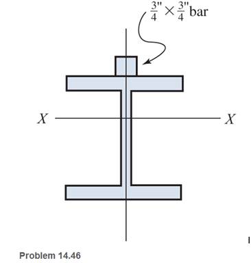
Ch. 14 - The beams of cross sections shown are subjected to...Ch. 14 - A solid rectangular simply supported timber beam 6...Ch. 14 - A W1430 supports the loads shown. Calculate the...Ch. 14 - If the allowable shear stress is 100 MPa,...Ch. 14 - A steel pin 112 in diameter is subjected to a...Ch. 14 - A timber power-line pole is 10 in. in diameter at...Ch. 14 - Calculate the value of S and Z and the shape...Ch. 14 - For beams that have cross sections as shown for...Ch. 14 - Calculate the maximum load P that the beam shown...Ch. 14 - A 412 (S4S) hem-fir timber beam carries a...Ch. 14 - A simply supported W1636 A992 steel beam carries a...Ch. 14 - A W250115 steel wide-flange section supports a...Ch. 14 - Assume that the floor joist dimensions of Example...Ch. 14 - Calculate the allowable superimposed uniformly...Ch. 14 - A 3 -in.-by- 12 -in. (S4S) scaffold timber plank...Ch. 14 - For the following computer problems, any...Ch. 14 - For the following computer problems, any...Ch. 14 - For the following computer problems, any...Ch. 14 - Calculate the section modulus with respect to the...Ch. 14 - The timber box section (a) of Problem 14.29 is...Ch. 14 - A timber beam is subjected to a maximum bending...Ch. 14 - Rework Problem 14.31 assuming that the beam is...Ch. 14 - A 12 -in.-diameter steel rod projects 2 ft...Ch. 14 - Calculate the maximum bending stress in a W530101...Ch. 14 - A cantilever cast-iron beam is 6 ft long and has a...Ch. 14 - 14.36 Calculate the moment strength for a...Ch. 14 - A W813 steel wide-flange beam on a 20 -ft span is...Ch. 14 - A simply supported beam with a cruciform cross...Ch. 14 - A rectangular beam 100 mm in width and 250 mm in...Ch. 14 - The timber box section (a) of Problem 14.29 is...Ch. 14 - For the I-shaped timber beam shown, calculate the...Ch. 14 - 14.42 A steel wide-flange beam is oriented so that...Ch. 14 - A W1045steel wide-flange beam supports a uniformly...Ch. 14 - 14.44 A steel wide-flange section is subjected to...Ch. 14 - A W30108 steel wide-flange beam is simply...Ch. 14 - A W612 is strengthened with a 34 -in.-by- 34 -in....Ch. 14 - Four wood boards 1 in. by 6 in. in cross section...Ch. 14 - A lintel consists of two 8 -in.-by- 12 in. steel...Ch. 14 - A 50 -mm-by- 300 -mm scaffold timber plank, placed...Ch. 14 - A laminated wood beam is built up by gluing...Ch. 14 - A rectangular hollow shape carries loads as shown....Ch. 14 - For the beam shown, calculate the maximum tensile...Ch. 14 - 14.53 A box beam is built up of four -in.-by--in....Ch. 14 - 14.54 Find the value of the loads P that can be...Ch. 14 - 14.55 Solve Problem 14.54 assuming that the timber...Ch. 14 - Calculate the values of S and Z and the shape...Ch. 14 - 14.57 A is supported on simple supports on a -ft...
Knowledge Booster


Learn more about
Need a deep-dive on the concept behind this application? Look no further. Learn more about this topic, mechanical-engineering and related others by exploring similar questions and additional content below.Similar questions
- Eight 7/8-in-diameter rivets fasten the plate in figure to the fixed member. Determine the average shearing stress caused in each rivet by the 10 ksi loads. What additional loads P can be applied before the shearing stress in any rivet exceeds 8000 psi? P 10 kips 3 in. 3 in. 3 in. 3 in. 3 in. P 4 in. 10 in. 10 kipsarrow_forwardQuestion 1 double-shear pin connections at Band D. All pins are 7 mm in diameter. a = 750 mm, b = 350 mm, h= 550 mm, P= 725 N, and 8 = 55° Determine the shear stress in pin B. Answer in MPa rounded-off to 2 decimal places. (1) a b Parrow_forwardUse the graphical method to construct the shear-force diagram and identify the magnitude of the largest shear force (consider both positive and negative). The ground reactions at the wall of the cantilever are provided. L₁= 14.75 ft L₂ = 7.75 ft Vc = 91.50 kips Mc = 706.4375 kip-ft 20 kips 6 kips/ft L₁ 103.50 kips 68.50 kips 91.50 kips O 79.50 kips O 114.50 kips 70 kips BO 12 kips/ft L2 O Vc Mcarrow_forward
- eBrandon Reardon Name 1. The lap joint shown is connected by four 20-mm diameter rivets. The load P is equal to 120 kN and is carried equally by the four rivets. How many shear planes are there? b. Determine the shear stress in the rivets in MPa. P=120 KN a. 160 mm | mm 12 mm A tie rod of 4 inch diameter is used to hold a plaster wall in place. The tensile stress in the rod caused by load P is 20 ksi. Find the diameter "d" (to the nearest 1/6 inch) of the washer that keep the bearing stress between the plaster and the washer from exceeding 300 psi. 2. Wall Tie rodarrow_forwardA bolt passing through a piece of wood is shown below. Determine the average shear stress in the wood.arrow_forward6. A shaft of different diameters is planted to the wall at A and is subjected to torque loadings, as shown. Determine the maximum shear stress in the shaft. A fillet weld having a radius of 5 mm is used to connect the shafts at B. (note: the stress concentration diagram is given) 1000 N·m 50 mm B 400 N·m 30 mm 250 N·m 2.0 1.9 1.8 1.7 1.6 K 1.5 1.4 1.3 1.2 1.1 1.0 0.00 0.05 0.10 ▬▬▬▬▬▬▬▬▬▬▬ T D 0.15 LE 0.20 D/d=2.5 0.25 2.0 1.67 1.25 1.11 0.30arrow_forward
- Answer p1 and Part 2: Determine the shear force acting at each of the following locations:(a) x = 11.0- ft (i.e., just to the left of point B)(b) x = 11.0+ ft (i.e., just to the right of point B)(c) x = 28.5 ftNote that x = 0 at support A. When entering your answers, use the shear-force sign convention detailed in Section 7.2.Answers: a) V = ____ kips b) V = ____ kips c) V = ____ kips Part 3: Determine the bending moment acting at each of the following locations:(a) x = 11.0 ft (i.e., at point B)(b) x = 28.5 ftNote that x = 0 at support A. When entering your answers, use the bending-moment sign convention detailed in Section 7.2. Answers: a) M = ____ kips-ft b) M = ____ kips-ft Part 4: Use your shear-force and bending-moment diagrams to determine the maximum bending moment, Mmax, and its location, xmax. Use the bending-moment sign convention detailed in Section 7.2.Answers: Mmax = ____ kips-ft xmax = ____ ftarrow_forwardThe axial stresses are 12 MPa C in the wood post B and 150 MPa T in the steel bar A as shown below. Pins at A, C, and D are smooth. Determine (a)The load P.(b)The minimum diameter for pin C if it is in single shear and the cross-shearing stress is limited to 70 MPa.(c)The minimum diameter for pin D if it is in double shear and the cross-shearing stress is limited to 70 MPa.arrow_forwardRequired information Link AB, of width b = 2 in. and thickness t= in., is used to support the end of a horizontal beam. The average normal stress in the link is -21 ksi and the average shearing stress in each of the two pins is 12 ksi. 4 NOTE: This is a multi-part question. Once an answer is submitted, you will be unable to return to this part. Determine the diameter d of the pins. The diameter d of the pins is in.arrow_forward
- 2. If the allowable shear stress for each of the steel pins at A and B is tpe 6.5 ksi and the allowable normal stress for bar CB is Operm 10 ksi, determine the diameter of the pins at A and B and that of the square bar CB. Pin A is in double shear while Pin B is in single shear. Ignore points D and E. (^ } 2.5 ft -3 ft -5 ft 150 lb/ft Fx =arrow_forwardA rectangular plate (0 =23°) is formed by welding two triangular plates shown in figure. The plate is subjected to a compressive stress of 2.3 MPa in the x-direction and a tensile stress of 13 MPa in the y-direction. Determine the normal and the shear stresses acting parallel to the weld. Weld Lütfen birini seçin: a. 10.664 MPa/5.50 MPa b. 0.3131 MPa/4.93 MPa c. None d. 0.0358 MPa/5.50 MPa e. 9.3175 MPa/6.09 MPaarrow_forwardAsaparrow_forward
arrow_back_ios
SEE MORE QUESTIONS
arrow_forward_ios
Recommended textbooks for you
 Elements Of ElectromagneticsMechanical EngineeringISBN:9780190698614Author:Sadiku, Matthew N. O.Publisher:Oxford University Press
 Mechanics of Materials (10th Edition)Mechanical EngineeringISBN:9780134319650Author:Russell C. HibbelerPublisher:PEARSON
 Thermodynamics: An Engineering ApproachMechanical EngineeringISBN:9781259822674Author:Yunus A. Cengel Dr., Michael A. BolesPublisher:McGraw-Hill Education
 Control Systems EngineeringMechanical EngineeringISBN:9781118170519Author:Norman S. NisePublisher:WILEY
 Mechanics of Materials (MindTap Course List)Mechanical EngineeringISBN:9781337093347Author:Barry J. Goodno, James M. GerePublisher:Cengage Learning
 Engineering Mechanics: StaticsMechanical EngineeringISBN:9781118807330Author:James L. Meriam, L. G. Kraige, J. N. BoltonPublisher:WILEY
Elements Of Electromagnetics
Mechanical Engineering
ISBN:9780190698614
Author:Sadiku, Matthew N. O.
Publisher:Oxford University Press
Mechanics of Materials (10th Edition)
Mechanical Engineering
ISBN:9780134319650
Author:Russell C. Hibbeler
Publisher:PEARSON
Thermodynamics: An Engineering Approach
Mechanical Engineering
ISBN:9781259822674
Author:Yunus A. Cengel Dr., Michael A. Boles
Publisher:McGraw-Hill Education
Control Systems Engineering
Mechanical Engineering
ISBN:9781118170519
Author:Norman S. Nise
Publisher:WILEY
Mechanics of Materials (MindTap Course List)
Mechanical Engineering
ISBN:9781337093347
Author:Barry J. Goodno, James M. Gere
Publisher:Cengage Learning
Engineering Mechanics: Statics
Mechanical Engineering
ISBN:9781118807330
Author:James L. Meriam, L. G. Kraige, J. N. Bolton
Publisher:WILEY
Differences between Temporary Joining and Permanent Joining.; Author: Academic Gain Tutorials;https://www.youtube.com/watch?v=PTr8QZhgXyg;License: Standard Youtube License