
(a)
The design of a plate girder for the given conditions, the selection of girder cross section and the required spacing of intermediate stiffeners by using LRFD.
Answer to Problem 10.7.8P
Four panels spaced at 58.25in.
Explanation of Solution
Given:
Span length
Uniformly distributed live load
Superimposed dead load
Concentrated dead load
Concentrated live load
Formula used:
h is the depth of web
Calculation:
Assume a girder weight of
Determine the factored loads:
The factored moment and shear are
Determine the overall depth:
Use the maximum permissible depth of 110 in.
Try
To determine the web thickness, first examine the limiting values of
For
Minimum
For
Minimum
Try a
Determine whether the web is slender:
Therefore, the web is slender.
Estimate required flange size:
Try a
Girder weight =
Compression flange:
Check flange local buckling (FLB):
Since
Compute the plate girder strength reduction factor:
Try a
Shear: At left end (end panel),
Required
From Table 3-17a in the Manual,
Use
This spacing will apply for the remaining distance to the centerline of the girder. This distance is
For a spacing a of 67 in., the number of panels is
Use 4 panels at
At
Required
For
Therefore, stiffeners are needed in middle
Conclusion:
Therefore, Use a
(b)
The size of intermediate and bearing stiffeners.
Answer to Problem 10.7.8P
2 PL
2 PL
Explanation of Solution
Given:
Span length
Uniformly distributed live load
Superimposed dead load
Concentrated dead load
Concentrated live load
Calculation:
Intermediate stiffener size:
Available width:
Try
To determine the required moment of inertia, use the conservative approximation from the User Note in AISC G2.3:
Try two
Length: From Figure 10.9 in the textbook (Steel design),
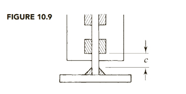
Assume a flange-to-web weld size of
Length =
Use two PL
Design the bearing stiffeners at the supports for a load of
Maximum stiffener width =
Try
Try two plates,
Bearing strength:
Compressive strength: The maximum permissible length of web is
Compute the radius of gyration about an axis along the middle of the web:
Compute the compressive strength:
Therefore,
Use 2 PL
Because there is a large difference between the reactions and the interior concentrated loads, use 2 PL
Conclusion:
Use two PL
(c)
The design of the all welds
Answer to Problem 10.7.8P
Explanation of Solution
Given:
Span length
Uniformly distributed live load
Superimposed dead load
Concentrated dead load
Concentrated live load
Calculation:
Design the flange-to-web welds.
The shear flow is
At the support,
Minimum weld size = 3/16 in. (AISC Table J2.4)
Minimum length =
Use 1.5 in.
Use E70 electrodes,
where D is weld size in sixteenths.
Try an
For two welds,
Weld strength =
Base metal shear yield strength (web plate controls) is
Shear rupture strength is
Weld strength controls.
For a 1.5-in. length,
Required spacing:
Since this is less than twice the length of the weld, use a continuous weld.
For
This occurs when
Maximum clear spacing: From AISC E6,
Maximum
For
Shear at first interior load, left of load, =
So maximum spacing will not be used in the first quarter of the span.
Spacing required at left side of first interior load is
Check middle fourth of span. Shear on right side of load is
Welds for intermediate stiffeners
Minimum weld size = 3/16in. (AISC Table J2.4)
Minimum length =
Use 1.5 in.
Use E70 electrodes,
where D is weld size in sixteenths.
Try
For four welds, the weld strength is
The base metal shear yield strength is
Shear rupture strength is
Weld strength controls.
For a 1.5-in. length,
The shear to be transferred is
A center-to-center spacing of 3 in. is equal to twice the length of the weld segment, so
either a continuous weld or an intermittent weld can be used. Use intermittent welds.
Maximum clear spacing: From AISC E6,
Maximum
Use
Welds for bearing stiffeners at the supports
Minimum weld size = 3/16in. (AISC Table J2.4)
Minimum length =
Use 1.5 in.
Use E70 electrodes,
where D is weld size in sixteenths.
Try
For four welds, the weld strength is
The base metal shear yield strength is
Shear rupture strength is
Weld strength controls.
For a 1.5-in. length,
The shear to be transferred is
Reaction
Use
Conclusion:
Use 3/16 in. continuous fillet welds for the first 20 ft,
Want to see more full solutions like this?
Chapter 10 Solutions
Steel Design (Activate Learning with these NEW titles from Engineering!)

- 1. Girders AC and DF have a width of 350 mm and a total depth of 500 mm. Given: Total dead load - 4.9 kPa (including wt. of slab and beam) Concrete f'e = 20.7 MPa Longitudinal bars fy = 415 MPa Live Load = 4.8 kPa Shear bars fyv = 275 MPa Distance on center of girders: Concrete cover = 70 mm L= 6 m, S = 2.8 m, Column = 0.35x0.35 a. ) For beam BE, calculate the factored shear force (kN) at the critical section. Assume a simply supported span. b.) Determine the spacing (mm) of two legs of 10 mm ø shear bars at the critical section. c. ) In accordance with NSCP provisions, what should be the maximum spacing (mm) of stirrups at the critical section of the shear. A 2.80 m E 2.80 m 6.00 m Girders 350x500 mm Beams 250x400 mmarrow_forwardLight-grade steel channel was used as a purlin of a truss. The top chord of the truss is inclined I V : 4 H and distance between trusses is equal to 6 m. The purlin has a weight of 79 N/m and spaced at 1.2 m. on centers. The dead load including the roof materials is 720 Pa, live load of 1000 Pa and wind load of 1.2 1.2 1440 Pa. Coefficient of Purlins pressure at leeward and windward are 0.6 and 0.2 respectively. Assume all loads passes through the centroid of the section. Properties of C 200 x 76 mm Sx = 6.19 x 104 mm Sy = 1.38 x 104 mm3 W = 79 N/m 1.2 Truss 1.2 12 12 1.2 Allowable bending stress Fbr = Fby = 207 MPa Truss %3D 6m O Calculate the bending stress, fox, for dead load and live load combination (D + L). Calculate the bending stress, foy, for dead load and live load combination (D + L). O Calculate the maximum ratio of actual to the allowable bending stress for load combination 0.75 (D + L + W) at the windward side. fbx = 151.14 MPa fby = 169.6 MPa Interaction = 1.25arrow_forward4/47 Compute the force in member HN of the loaded truss. BE 2 m A 4/40 n L L D R Q L L F 6 m L P O N -8 panels at 3 m Problem 4/47 age to L BODJEN H M L I L L 2- J [2 m EM Karrow_forward
- S f A structure is to be built as shown supporting a uniform load of 18 kN/m. The location for the supports at A and B has been determined. The connection at C may be placed anywhere along the member AD 18 kN/m A C D 3 m B L -7 mi -5 m- If the allowable bending stress for member AD is 8 MPa, which among the choices gives the most economic section? Select the correct response: 275 mm x 550 mm 250 mm x 500 mm 300mm x 600 mm 225 mm x 450 mm rigidarrow_forward4-1 Figure P4.1 shows a simply supported beam and the cross section at midspan. The beam supports a uniform service (unfactored) dead load consisting of its own weight plus 1.4 kips/ft and a uniform ser- vice (unfactored) live load of 1.5 kips/ft. The con- crete strength is 3500 psi, and the yicld strength of the reinforcement is 60,000 psi. The concrete is normal-weight concrete. Use load and strength- reduction factors from ACI Code Sections 9.2 and 9.3. For the midspan section shown in Fig. P4-1b, compute M, and show that it exceeds Mu- Wo = 14 kips/it plus weight of beam WL - 1.5 kipa/it (a) 20 ft 21.5 in. 24 in. (b) 3 No. 9 bars 12 in. Fig. P4-1arrow_forwardWhere is/are the location(s) of the maximum transverese shear stress? A simple I-beam is loaded as shown. 20 mm P KN PKN PKN Į Į -C B с D L/4 m L/4 m Midspan at point C Roller at E at the NA Section B at the top fiber Pin A at point C Midspan at point D Roller E at point D L/4 m L/4 m OE 20 mm 20 mm- 250 mm 150 mm 150 mm Aarrow_forward
- Figure 1.5 m E -2 m- 3 kN D B -2 m 1 of 1 Identify the zero-force members in the truss. Check all that apply. BE DE CD AB AE BD BC Submit Drouido Foodbook Request Answerarrow_forwardA Mansard roof truss is loaded as shown. Determine the force in members DF, DG, and EG. 3 m ✓ A 1.2 kN 1.2 kN 1.2 kN 1.2 kN 1.2 kN B D C E| k 2.25 m 4 m. F G 4 m- H -4 m I 4 K OL 2.25 m Show complete solutions and diagrams. Original work please I will upvotearrow_forwardThe uniformly distributed live load on the floor plan in the figure given below is 65 lb/ft². Consider the live load reduction if permitted by the ASCE standard. A (B) B2 G3 -6 @ 6.67' = 40- I B4 G4 B1 40' G1 C2 G2 C3 Establish the loading for girder G3. The loading (P) for girder G3 is [ B3 20' kips. (3) 2 @ 10' = 20' I+ 5 @ 8'=40'arrow_forward
- A W350x90 girder 8m long carries a concentrated dead load, P at every quarter points and a uniform dead load of 5 kN/m (including dead weight) amd a uniform live load of 7.2 kN/m. CIVIL ENGINEERING STEEL Properties: A = 11,500 mm² tw = 10 mm tf = 16 mm mm Ix=1119.7 x 10 mm* Allowable Stresses: Fb = 0.66 Fy d = 350 mm bf = 250 mm tf = 16 mm Fv = 0.40 Fy a.) Determine P base on Flexure. b.) Determine P base on Shear. b.) Determine P base on Deflection. DESIGN Sallow=1/360arrow_forwardure B 2m2 m C -2 m D 4 m 500 N 700 N 2 of 2 Part B Identify the zero-force members in the truss shown in (Figure 2). Check all that apply. 000 CD DE CG CF FG BC BG DF AG EF AB Submit Provide Feedback Request Answerarrow_forwardA plate girder cross section consists of two flanges, 11⁄2 inchesx 15 inches, and a 5⁄16-inch 3 66-inch web. A572 Grade 50 steel is used. The span length is 55 feet, the service live load is 2.0 kips/ft, and the dead load is 0.225 kips/ft, including the weight of the girder. Bearing stiffeners are placed at the ends, and intermediate stiffeners are placed at 69-20 and 12,-9,, from each end. Does this girder have enough shear strength? a. Use LRFD. b. Use ASDarrow_forward
 Steel Design (Activate Learning with these NEW ti...Civil EngineeringISBN:9781337094740Author:Segui, William T.Publisher:Cengage Learning