
Concept explainers
Videos
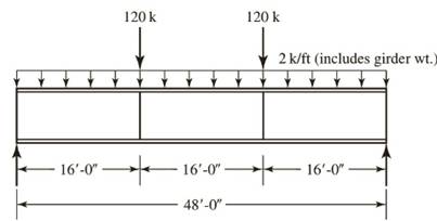
A plate girder must be designed for the conditions shown in Figure P10.7-4. The given loads are factored, and the uniformly distributed load includes a conservative estimate of the girder weight. Lateral support is provided at the ands and at the load points. Use LRFD for that following:
a. Select the, flange and web dimensions so that intermediate stiffeners will he required. Use
b. Determine the locations of the intermediate stiffeners, but do not proportion them.

Trending nowThis is a popular solution!

Chapter 10 Solutions
Steel Design (Activate Learning with these NEW titles from Engineering!)


- A W18 x 86 beam is riveted to a W24 x 117 girder by a connection as shown. The diameter of the rivets is 7/8 in., and the angles are each 4 x 31/2 x 3/8 in. For each rivet, assume that the allowable stresses are t = 15 ksi and ₁ = 32 ksi. Find the allowable load (kips) on the connection. Girder Beam Relevant data from the table (Appendix B of textbook): Properties of Wide-Flange Sections (W shapes): U.S. Customary Units Designation W18 x 86 W24 x 117 Web thickness 0.480 in 0.550 in Carrow_forwardW3D 25 Y= 155 %31 1oow= 2500 KN 27=310mm X= 475 Z= 60 %3D 102=600mmarrow_forwardSTRENGTH OF MATERIALS (Please write the complete solutions, FBD and answer in 4 decimal place. Rate/thumbs up will be given. For the given loaded truss, the allowable tensile stress in any member is up to 800 MPa while the allowable compressive stress is up to 650 MPa. The reduced stress in compression is specified to reduce the danger of buckling. Determine the minimum cross-sectional area of member BE. B 3m A, 4m C 4m E 4m G 4m |RA 96 kN 200 kN 96 kN |RHarrow_forward
- A W18 x 86 beam is riveted to a W24 x 117 girder by a connection as shown. The diameter of the rivets is 7/8 in., and the angles are each 4 x 31/2 x 3/8 in. For each rivet, assume that the allowable stresses are t = 15 ksi and o, = 32 ksi. Find the allowable load (kips) on the connection. Relevant data from the table (Appendix B of textbook): Properties of Wide-Flange Sections (W shapes): U.S. Customary Units Designation w18 x 86 Web thickness 0.480 in W24 x 117 0.550 in Beam Girderarrow_forwardThe given girder has beams framing into it at the ends and at every L/3 point. The beam carries a service live load of 20 kips as shown and superimposed uniformly distributed service dead load of 10 kip/ft. Select the lightest A992 W-section that can carry the load. Do not check for deflection. P, = 20 kips LL PLL W. = 10 kip/ft DL = 20 ft WDL L/3 BEAMS FRAMING INTO GIRDER Larrow_forwardTASK 3 250 180 14 I 30 24 Weld 450 A compound girder consists of a steel joist with steel plates welded onto each flange as shown. If the ends are simply supported and the effective span is 10 m, what is the maximum UDL which can be supported by the girder? [kN/m] Allowable longitudinal stress in plates = 110 MN/m² Allowable load in shear for each weld = 60 kN/m Allowable shearing stress in web of girder = 75 MN/m² Note: 1.0 MN/m² = 1.0 N/mm² 50arrow_forward
- AW 12 x 65 column section shown in the figure is pinned at each end and has an additional support in the weak direction at a point 4.1 m from the top. Use X- 4.8 m K 1 for both directions. X+Y Properties of W 12 x 65 A 12323 mm2 - 134.11 mm ry 76.71 mm Fy- 248 MPa Determine the allowable compressive strength (kN).arrow_forwardBearing P plate Let the allowable stresses in the post be ost=120MPaand oco=6MPA. Compute the maximum safe axial load P that may be applied. The moduli of elasticity are 200 GPafor steel and 14 GPafor a concrete. Each steel bar has cross-sectional area of 900mm2. Steel - Concrete - 300 mm 300 mmarrow_forward1. For the Pratt bridge truss and the loading shown below, determine the average normal stress in member BE, knowing that the cross-sectional area of that member is 60 in². NN K 12-12--12--12--| 50 lips 50 kips 50. ips Figure 1 G xfonearrow_forward
- USE NSCP 2010 A rectangular beam reinforced for both tension and compression barshas an area of 1450 mm² for compression bars and 4350 mm² fortension bars. The tension bars and compression bars are placed at a distance of 600 mm and 62.5 mm respectively from the top of thebeam. The beam width 300 mm, fc’ = 21 MPa, fy = 415 MPa andtension steel covering is 60 mm.If it is 8 m-simply-supported beam that carries three concentratedservice live loads P applied at three quarter points of the beam (exceptat the supports), neglecting the self weight of the beam, determine themaximum value of service load P in kiloNewtons.arrow_forwardA. A truss member is made with a pair of 4"x 3" x 3/8" angles with the long legs back to back. The angles are 36 ksi steel and are attached at the connection by a 3/8 in. plate running between the angles. The unbraced length is 12 feet and consider both ends fixed. What is the allowable axial load in compression? In tension? How does the compression capacity change if I connect them with a %" plate in between? Does it change tension capacity? (a) 12 C. A 28 foot column is braced top and bottom about the X-X axis and has K bracing as shown on the Y-Y axis only. It is built of A36 steel and is a W12 x 30 section. Can it support an axial load of 165 kips? State its actual capacity.arrow_forwardEach bar of the truss has a rectangular cross section, 30 mm by 60 mm. Determine the maximum vertical load P that can be applied at B if the working stresses are 100 MPa in tension and 80 MPa in compression. (A reduced stress in compression is specified to reduce the danger of buckling.) B 8m Gm 10marrow_forward
 Steel Design (Activate Learning with these NEW ti...Civil EngineeringISBN:9781337094740Author:Segui, William T.Publisher:Cengage Learning