
Concept explainers
Videos
Use the method of superposition to solve the following problems and assume that the flexural rigidity El of each beam is constant.
9.90 Before the load P was applied, a gap, δ0 = 0.5 mm, existed between the cantilever beam AC and the support at B. Knowing that E = 200 GPa, determine the magnitude of P for which the deflection at C is 1 mm.
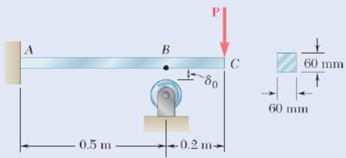
Fig. P9.90
Find the magnitude of load P for the given condition using superposition method.
Answer to Problem 90P
The magnitude of load P in the beam is
Explanation of Solution
Given information:
The gap at the point B is
The modulus of elasticity of the material is
The size of the square cross section is
The deflection at point C is
Calculation:
Find the moment of inertia of the square cross section (I) using the relation.
Here, the size of the square cross section is a.
Substitute 60 mm for a.
Consider the portion AB of the beam.
The load P at point C will be converted into a load and moment at point B.
Show the free-body diagram of the superimposed beam AB as in Figure 1.
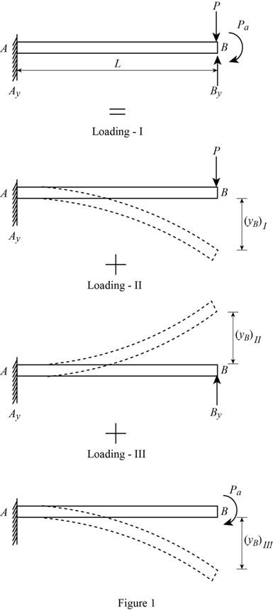
Loading I:
The downward load P is acting at point B of the beam.
Refer to Case 1 in Appendix D “Beam Deflections and Slopes” in the textbook.
Write the deflection equation for concentrated load acting in a cantilever beam as follows;
Find the deflection at point B due to load P at point B as follows;
Loading II:
The upward reaction
Refer to Case 1 in Appendix D “Beam Deflections and Slopes” in the textbook.
Write the deflection equation for concentrated load acting in a cantilever beam as follows;
Find the deflection at point B due to reaction at point B as follows;
Loading III:
The clockwise moment is acting at point B of the beam.
Refer to Case 3 in Appendix D “Beam Deflections and Slopes” in the textbook.
Write the deflection equation for moment in a cantilever beam as follows;
Find the deflection at point B due to the moment at point B as follows;
Find the resultant deflection at point B as follows.
Substitute
Substitute 0.5 mm for
Consider the beam ABC.
Show the free-body diagram of the superimposed beam ABC as in Figure 2.
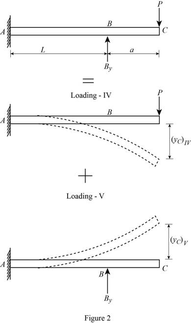
Loading IV:
The downward load P is acting at point C of the beam.
Refer to Case 1 in Appendix D “Beam Deflections and Slopes” in the textbook.
Write the deflection equation for concentrated load acting in a cantilever beam as follows;
Find the deflection at point C due to load P at point C as follows;
Loading V:
The upward reaction
Refer to Case 1 in Appendix D “Beam Deflections and Slopes” in the textbook.
Write the slope and deflection equation for concentrated load acting in a cantilever beam as follows;
Find the deflection at point B due to reaction at point B as follows;
Find the slope at point B due to reaction at point B as follows;
The portion BC remains straight.
Find the deflection at point C due to reaction at point B as follows;
Substitute
Find the resultant deflection at point C as follows.
Substitute
Substitute 1 mm for
Solve the Equation (1) and (2).
Therefore, the magnitude of load P in the beam is
Want to see more full solutions like this?
Chapter 9 Solutions
Mechanics of Materials, 7th Edition


- An overhang beam with negligible weight is loaded as shown. Knowing that the flexural rigidity of the beam is El = 2 × 10⁵ kNm², (a) Reactions at A and B (a) determine the reactions at supports A and B, (b) derive the elastic (b) section AB curve for section AB, (c) derive the elastic curve for section BC, and v = (d) determine the deflection at point C. v = (c) section BC v' = 2 kN/m v = (d) m marrow_forwardProblem 7.25 Consider the beam shown in (Figure 1). Solve this problem using the conjugate-beam method. Take E = 200 GPa, I = 710(106) mm². Figure 1.5 m 90 kN-m + 1.5 m 1 of 1 30 kN 2 C Part B Determine the slope at B measured counterclockwise from the positive axis. Express your answer using three significant figures. IVE ΑΣΦ | OB = Submit Part C Amax = Request Answer Submit Determine the maximum displacement of the beam measured upward. Express your answer to three signif I μÅ Value vec Request Answer ? Units figures and include the appropriate units. ? radarrow_forwardA beam ABCD, 6 m long, is simply-supported at the right-hand end D and at a point B 1 m from the left hand end A. It carries a vertical load of 10 kN at A, a second concentrated load of 20 kN at C, 3 m from D, and a uniformly distributed load of 10 kN/m between C and D. Determine the position and magnitude of the maximum deflection if E = 208 GN/m2 and I = 35 x10^-6 m4.arrow_forward
- 3(a). Both portions of the rod ABC are made of an aluminum for which E= 60 GPa. Knowing that the magnitude of P is 3 kN, determine (a) the value of Q so that the deflection at A is zero, (b) the corresponding deflection at B. Figure 3 1.5mm diameter 1.0⁰m 50-mm diameter WSTEarrow_forwardProblem 14.2. Determine the maximum deflection of the cantilevered beam. The beam is made of material having E = 200 GPa and I= 65.0*10° mm. 15kN 30 kN/m M RA -1.5 m 1.5 m- R =37.5kN; M =67.5kNmarrow_forwardb. Determine the deflection of the beam at midpoint for the beam loading system shown in the figure given below : Take : E = 200 GN/m2 and I = 83 x 106 m. 20 N 30 N 10 N/m 10 m 5 m 10 m Fig. 10.arrow_forward
- A uniformly distributed load of 2.2 KN/m is supported by two beams arranged as shown below. Beam AB is fixed at the wall and beam CD is simply supported. Before the load is applied, the beams are in contact at B, but the reaction at B is zero. Each beam is 62.5 mm wide by 90 mm high. The modulus of elasticity of the material is 8.25 GPa. Determine (a)The deflection at B when the load is applied.(b)The maximum bending stress in beam AB.(c)The maximum shearing and bending stress in beam CD.arrow_forwardProblem 1: Determine the horizontal and vertical deflections at B of the truss. 10 ft D 5 ft (4 in.²) (6 in.²) 20 k E 20 ft E 10,000 ksi (6 in.) Problem 2: Determine the smallest cross-sectional area A for the members of the truss shown, so that the vertical deflection at B does not exceed 0.4 inches. 10 k B 2 at 6 ft 12 ft EA= constant E = 1,600 ksi a-6.5 (10 F 10 k H B 45 k F Problem 3: Determine the vertical deflection at G of the truss due to a temperature increase of 65°F in AB, BC, CD, and DE, and a temperature drop of 20°F in FG and GH. 4 at 12 ft 48 t 3 ft 12 ftarrow_forwardProblem 7.25 Consider the beam shown in (Figure 1). Solve this problem using the conjugate-beam method. Take E = 200 GPa, I = 710(106) mm². Figure 1.5 m 90 kN-m + 1.5 m 1 of 1 30 kN 2 C Part B Determine the slope at B measured counterclockwise from the positive axis. Express your answer using three significant figures. OB = Submit Part C Amax = VAΣo↓vec Submit Request Answer Determine the maximum displacement of the beam measured upward. Express your answer to three signific figures and include the appropriate units. I μÅ Value Request Answer Units ? ? radarrow_forward
- Problem 5.2 Determine the deflection at x=1m and x=4m. Specify the slope at A and the maximum deflection. El is constant. A -2 m X 6 kN 6 m C 6 kN 6 m 2 m Barrow_forwardPROBLEM 9.11 Mo (a) Determine the location and magnitude of the maximum deflection of beam AB. (b) Assuming that beam AB is a W360 x 64, L = 3.5 m, and E = 200 GPa, calculate the maximum allowable value of the applied moment Mo if the maximum deflection is not to excecd I mm. Mo = 45.3 kN · m %3Darrow_forwardPROBLEM 4.The beam AB consisting of a cast iron plate of uniform thickness, b, and length, L, is to support the distributed load w(x) shown a) Knowing that the beam is to be of constant strength (fully stressed beam), express h in terms of x, L and ho. b) Determine the smallest value of ho if L=800 mm, b=25 mm, wg=300 kN/m and oai=200 MPa. w-w.cos(Tx/2L) ho Barrow_forward
 Elements Of ElectromagneticsMechanical EngineeringISBN:9780190698614Author:Sadiku, Matthew N. O.Publisher:Oxford University Press
 Mechanics of Materials (10th Edition)Mechanical EngineeringISBN:9780134319650Author:Russell C. HibbelerPublisher:PEARSON
 Thermodynamics: An Engineering ApproachMechanical EngineeringISBN:9781259822674Author:Yunus A. Cengel Dr., Michael A. BolesPublisher:McGraw-Hill Education
 Control Systems EngineeringMechanical EngineeringISBN:9781118170519Author:Norman S. NisePublisher:WILEY
 Mechanics of Materials (MindTap Course List)Mechanical EngineeringISBN:9781337093347Author:Barry J. Goodno, James M. GerePublisher:Cengage Learning
 Engineering Mechanics: StaticsMechanical EngineeringISBN:9781118807330Author:James L. Meriam, L. G. Kraige, J. N. BoltonPublisher:WILEY