
Applied Statics and Strength of Materials (6th Edition)
6th Edition
ISBN: 9780133840544
Author: George F. Limbrunner, Craig D'Allaird, Leonard Spiegel
Publisher: PEARSON
expand_more
expand_more
format_list_bulleted
Concept explainers
Videos
Textbook Question
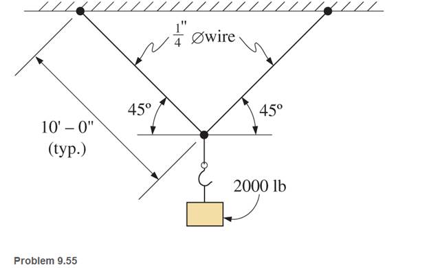
Chapter 9, Problem 9.55SP
A hook is suspended by two steel wires, as shown. The wires are
Expert Solution & Answer
Want to see the full answer?
Check out a sample textbook solution
Students have asked these similar questions
Two steel pipes are used to support a 50KN load, as shown below. The pipes are connected
to the wall (at points A and C) and each other (at point B) with pin joints. The load is applied
at point B.
a. Draw free body diagrams for the two pipes and the pin joint at point B.
b. Find the support forces at the wall at points A and C.
1.25m
A
50KN
1.15m
A homogeneous 200 kg bar with a length of 6 meters carries a 3 kN force at one end. This bar is supported at the other end by a pin on the wall and the center with 10 mm diameter cable attached to the same wall 4 meters above the pin. What is the tensile load on the cable.
Figure 1 below shows the bronze and galvani pipes are fastened to rigid supports at ends A and B and to a rigid plate C at their junction. The bronze pipe is twice as long as the galvani pipe. Two equal and symmetrically placed loads P act on the plate at C.
Chapter 9 Solutions
Applied Statics and Strength of Materials (6th Edition)
Ch. 9 - Write the direct stress formula in its three forms...Ch. 9 - A 6-in-diameter concrete test cylinder is loaded...Ch. 9 - Determine the tensile stress in each segment of...Ch. 9 - Calculate the stress developed in the following...Ch. 9 - The following members are subjected to axial...Ch. 9 - Determine the stresses in the two segments of the...Ch. 9 - A bin weighing 8 tons is supported by three steel...Ch. 9 - Diameters of small commercially available steel...Ch. 9 - A No. 32 (metric designation) reinforcing bar for...Ch. 9 - In the bolted connection of Figure 9.12 , assume...
Ch. 9 - Compute the force required to punch a...Ch. 9 - The 34 — in. — diameter bolt shown is subjected to...Ch. 9 - Why is strain unitless (or dimensionless)?Ch. 9 - (a) Given =1.2in. and L=100ft calculate (b) Given...Ch. 9 - A short compression member 2 in. by 2 in. in cross...Ch. 9 - A 100-ft-long rod is suspended from one end. The...Ch. 9 - Compute the total elongation of a steel bar,...Ch. 9 - A steel rod 34 in. in diameter and 25 ft long is...Ch. 9 - An aluminum rod 25mm in diameter and 4m long is...Ch. 9 - A steel rod 10 ft long is made up of two 5 ft...Ch. 9 - A titanium alloy bar elongates 0.500 in. when...Ch. 9 - Write a program that will calculate the allowable...Ch. 9 - Write a program that will compute stress, strain,...Ch. 9 - The Viking Bin Company manufactures suspended bins...Ch. 9 - Write a computer program that will calculate the...Ch. 9 - The joint between a diagonal and a chord in a...Ch. 9 - In Problem 9.26, find the required length of the...Ch. 9 - A column is supported by a base plate, pedestal,...Ch. 9 - If the soil pressure under the footing of Problem...Ch. 9 - A hopper weighing 75 kN is supported by three...Ch. 9 - A steel bar has a rectangular cross section 25 mm...Ch. 9 - A steel wire is suspended vertically from its...Ch. 9 - A W1240 shape is subjected to a tensile load of...Ch. 9 - Calculate the required diameter of steel tie rods...Ch. 9 - A 30-ft-long steel rod of circular cross section...Ch. 9 - Consider the bolted lap joint shown in Figure...Ch. 9 - An inclined member is braced with a glued block,...Ch. 9 - Calculate the force a punch press must exert if it...Ch. 9 - A 34 - in. - diameter punch is used to punch a...Ch. 9 - A control arm is keyed to a 1-in. -diameter shaft...Ch. 9 - Calculate the required width b for the key of...Ch. 9 - A 25-mm-diameter aluminum rod, 3 m long, is...Ch. 9 - A short timber post of Douglas fir is subjected to...Ch. 9 - A 1 00-ft surveyor’s steel tape with a...Ch. 9 - An 18-in-long steel rod is subjected to a tensile...Ch. 9 - Compute the magnitude of the tensile load that...Ch. 9 - A 5-mm-diameter steel wire, 18 m in length, is...Ch. 9 - A structural steel rod 112 in. in diameter and 20...Ch. 9 - A rectangular structural steel eyebar 34 in. thick...Ch. 9 - 9.50 A
in. — diameter steel rod, 100 ft long, is...Ch. 9 - For the truss shown, compute the total deformation...Ch. 9 - A steel bar with a cross section of 12 in. by 12...Ch. 9 - Rework Problem 9.52 , changing the second load...Ch. 9 - In the structure shown, the tie-back BC is a round...Ch. 9 - A hook is suspended by two steel wires, as shown....Ch. 9 - The trolley of a small hoist is supported on a...Ch. 9 - The steel piston rod to the master cylinder has a...Ch. 9 - A stranded steel brake cable is composed of 7...Ch. 9 - The piston of a steam engine is 400 mm in diameter...
Knowledge Booster


Learn more about
Need a deep-dive on the concept behind this application? Look no further. Learn more about this topic, mechanical-engineering and related others by exploring similar questions and additional content below.Similar questions
- The figure shows a setup where when the member AB is horizontal and the unstretched aluminum bar length 2 m is attached to end D, the steel bar A has a gap of 3 mm with the support at Cas shown by A in the figure. At that point the system is deformed and the steel bar is attached to the support C. After this is done and all external forces are removed compute (a) the forces in both the steel and the aluminum bars. 0.75 m 1.5 m Steel A = 250 mm? E = 200 GPa Aluminum L= 2 m A = 300 mm E = 70 GPa Figure P-242arrow_forward2. A steel strut, 40 mm diameter, is turned down to 20 mm diameter for one-half its length. Calculate the ratio of the extensions in the two parts due to axial loading.arrow_forward6 if 1000 lbs is applied at Point A. What is the applied gravity load at point B? What is force Ph? What is force Pv?arrow_forward
- A derrick is shown in the figure supporting a 2,461 N load. The vertical beam has a ball and socket connection into the ground at D and is held by guy wires AC and BC. Neglecting the weight of the members and guy wires. Compute the tension of guy wires CE in N. Write numerical value only and in 2 decimal places. 8m 10m 7.5m 4m d 8.5m 7.5marrow_forwardDraw all forces acting on member ABEG here: A B E O GOarrow_forwardThe three bars shown in fig are pined at point B which carry a load P and fixed at points A, C and D . The length of the three bars AB, BD and CB is (L) . The cross section area for each bar is Aj except the bar CB which has different cross section area of A2 . All three bars have the same young modulus E. Determine the axial force in each of the bars.arrow_forward
- (4) The Jib crane shown in figure carries load of W. If the maximum load in the tie is 25 kN, calculate the value of W and the load on the jib.arrow_forward4. A spherical weather balloon is made of 0.2-mm-thick fabric that has a tensile strength of 10 MPa. The balloon is designed to reach an altitude where the interior pressure is 1500 Pa above the atmospheric pressure. Find the largest allowable diameter of the balloon, using 1.5 as the factor of safety.arrow_forwardFor the figure shown below, compute the shear force in section 1. Neglect the weights of the member. Note that point B is pin-connected. 50KN ... 2m. B 5m 5m 5marrow_forward
- An iron rod 5 m long and having a 10 mm outside radius and 4 mm inside radius stretches 1 mm when a mass of 255 kg hangs on it. Compute the modulus of elasticity of the iron. note: answer must be in GPaarrow_forwardThe spinning wheel, as shown in the figure, is subjected to a load of 200 lb. F calculate the horizontal force vectorarrow_forwardThis arm is attached to a wall on the left. The right end is free hanging. Each section is 2.0m wide and 3.0m high. If the force at the end of the arm is F = 200.0N, what is the force in member 9? Use the Method of Sections. Use a positive number if it is in tension and a negative number if it is in compression.arrow_forward
arrow_back_ios
SEE MORE QUESTIONS
arrow_forward_ios
Recommended textbooks for you
 Elements Of ElectromagneticsMechanical EngineeringISBN:9780190698614Author:Sadiku, Matthew N. O.Publisher:Oxford University Press
 Mechanics of Materials (10th Edition)Mechanical EngineeringISBN:9780134319650Author:Russell C. HibbelerPublisher:PEARSON
 Thermodynamics: An Engineering ApproachMechanical EngineeringISBN:9781259822674Author:Yunus A. Cengel Dr., Michael A. BolesPublisher:McGraw-Hill Education
 Control Systems EngineeringMechanical EngineeringISBN:9781118170519Author:Norman S. NisePublisher:WILEY
 Mechanics of Materials (MindTap Course List)Mechanical EngineeringISBN:9781337093347Author:Barry J. Goodno, James M. GerePublisher:Cengage Learning
 Engineering Mechanics: StaticsMechanical EngineeringISBN:9781118807330Author:James L. Meriam, L. G. Kraige, J. N. BoltonPublisher:WILEY
Elements Of Electromagnetics
Mechanical Engineering
ISBN:9780190698614
Author:Sadiku, Matthew N. O.
Publisher:Oxford University Press
Mechanics of Materials (10th Edition)
Mechanical Engineering
ISBN:9780134319650
Author:Russell C. Hibbeler
Publisher:PEARSON
Thermodynamics: An Engineering Approach
Mechanical Engineering
ISBN:9781259822674
Author:Yunus A. Cengel Dr., Michael A. Boles
Publisher:McGraw-Hill Education
Control Systems Engineering
Mechanical Engineering
ISBN:9781118170519
Author:Norman S. Nise
Publisher:WILEY
Mechanics of Materials (MindTap Course List)
Mechanical Engineering
ISBN:9781337093347
Author:Barry J. Goodno, James M. Gere
Publisher:Cengage Learning
Engineering Mechanics: Statics
Mechanical Engineering
ISBN:9781118807330
Author:James L. Meriam, L. G. Kraige, J. N. Bolton
Publisher:WILEY
Types Of loads - Engineering Mechanics | Abhishek Explained; Author: Prime Course;https://www.youtube.com/watch?v=4JVoL9wb5yM;License: Standard YouTube License, CC-BY