
Loose Leaf for Engineering Circuit Analysis Format: Loose-leaf
9th Edition
ISBN: 9781259989452
Author: Hayt
Publisher: Mcgraw Hill Publishers
expand_more
expand_more
format_list_bulleted
Concept explainers
Videos
Textbook Question
Chapter 7.2, Problem 4P
7.4 The current through a 200 mH inductor is shown in Fig. 7.13. Assume the passive sign convention, and find vL at t equal to (a) 0; (b) 2 ms; (c) 6 ms.
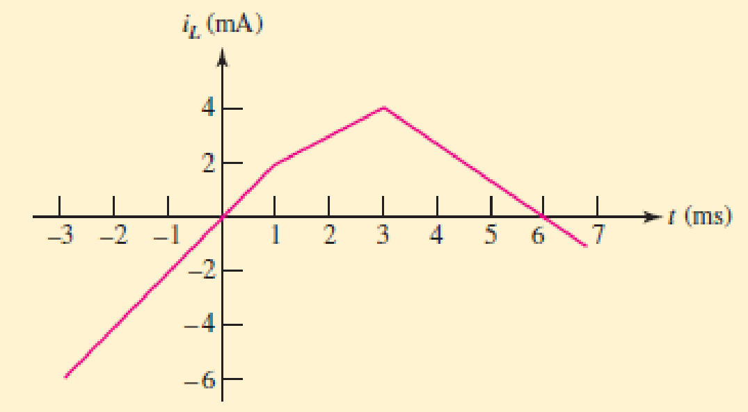
■ FIGURE 7.13
Expert Solution & Answer
Want to see the full answer?
Check out a sample textbook solution
Students have asked these similar questions
7.49.2 For the RC circuit shown in the image below, the current waveform is applied.
If v (0) = 0, R1 = 4 S2 and R2 = 9 $2, determine the voltage across the capacitor, v
when t = 1.1 s. Please pay attention: the numbers may change since they are
randomized. Your answer must include 3 places after the decimal point, and the
proper SI unit.
is (A) A
1
t (s)
(a)
R2
+
is
R,
0.5 F
(b)
Your Answer:
Answer
units
7.11.1 For the RL circuit shown in the image below, the switch has been closed for a
long time, and it opens at t= 0. If R1 = 6 S2 and R2 = 4 S2, determine the energy
stored in the inductor when t = 0. Please pay attention: the numbers may change
since they are randomized. Your answer must include 3 places after the decimal
point, and the proper Sl unit.
t = 0
R1
4 H
ell
24 V(+
4Ω
R2
Your Answer:
Answer
units
Question 32
Determine an equivalent inductance for the network shown in Fig. 7.54 if each inductor has value L.
O
rele
Ay
ell
FIGURE 7.54
rell
Chapter 7 Solutions
Loose Leaf for Engineering Circuit Analysis Format: Loose-leaf
Ch. 7.1 - Determine the current flowing through a 5 mF...Ch. 7.1 - Prob. 2PCh. 7.1 - Prob. 3PCh. 7.2 - 7.4 The current through a 200 mH inductor is shown...Ch. 7.2 - The current waveform of Fig. 7.14a has equal rise...Ch. 7.2 - Prob. 6PCh. 7.2 - Let L = 25 mH for the inductor of Fig. 7.10. (a)...Ch. 7.3 - Find Ceq for the network of Fig. 7.23. FIGURE...Ch. 7.4 - If vC(t) = 4 cos 105t V in the circuit in Fig....Ch. 7.5 - Derive an expression for vout in terms of vs for...
Ch. 7.6 - Prob. 11PCh. 7 - Making use of the passive sign convention,...Ch. 7 - Prob. 2ECh. 7 - (a) If the voltage waveform depicted in Fig. 7.42...Ch. 7 - A capacitor is constructed from two brass plates,...Ch. 7 - Prob. 5ECh. 7 - Prob. 6ECh. 7 - Design a capacitor whose capacitance can be varied...Ch. 7 - Design a capacitor whose capacitance can be varied...Ch. 7 - Prob. 9ECh. 7 - Assuming the passive sign convention, sketch the...Ch. 7 - Prob. 11ECh. 7 - Prob. 12ECh. 7 - Prob. 13ECh. 7 - Calculate the power dissipated in the 40 resistor...Ch. 7 - Prob. 15ECh. 7 - Design a 30 nH inductor using 28 AWG solid soft...Ch. 7 - Prob. 17ECh. 7 - Prob. 18ECh. 7 - Prob. 19ECh. 7 - Prob. 20ECh. 7 - Calculate vL and iL for each of the circuits...Ch. 7 - The current waveform shown in Fig. 7.14 has a rise...Ch. 7 - Determine the inductor voltage which results from...Ch. 7 - Prob. 24ECh. 7 - The voltage across a 2 H inductor is given by vL =...Ch. 7 - Calculate the energy stored in a 1 nH inductor if...Ch. 7 - Determine the amount of energy stored in a 33 mH...Ch. 7 - Making the assumption that the circuits in Fig....Ch. 7 - Calculate the voltage labeled vx in Fig. 7.52,...Ch. 7 - Prob. 30ECh. 7 - Prob. 31ECh. 7 - Determine an equivalent inductance for the network...Ch. 7 - Using as many 1 nH inductors as you like, design...Ch. 7 - Compute the equivalent capacitance Ceq as labeled...Ch. 7 - Prob. 35ECh. 7 - Prob. 36ECh. 7 - Reduce the circuit depicted in Fig. 7.59 to as few...Ch. 7 - Refer to the network shown in Fig. 7.60 and find...Ch. 7 - Prob. 39ECh. 7 - Prob. 40ECh. 7 - Prob. 41ECh. 7 - Prob. 42ECh. 7 - Prob. 43ECh. 7 - Prob. 44ECh. 7 - Prob. 45ECh. 7 - Prob. 46ECh. 7 - Prob. 47ECh. 7 - Let vs = 100e80t V with no initial energy stored...Ch. 7 - Prob. 49ECh. 7 - Prob. 50ECh. 7 - Interchange the location of R1 and Cf in the...Ch. 7 - For the integrating amplifier circuit of Fig....Ch. 7 - Prob. 53ECh. 7 - For the circuit shown in Fig. 7.73, assume no...Ch. 7 - A new piece of equipment designed to make crystals...Ch. 7 - An altitude sensor on a weather balloon provides a...Ch. 7 - One problem satellites face is exposure to...Ch. 7 - The output of a velocity sensor attached to a...Ch. 7 - A floating sensor in a certain fuel tank is...Ch. 7 - (a) If Is = 3 sin t A, draw the exact dual of the...Ch. 7 - Draw the exact dual of the simple circuit shown in...Ch. 7 - (a) Draw the exact dual of the simple circuit...Ch. 7 - (a) Draw the exact dual of the simple circuit...Ch. 7 - Prob. 64ECh. 7 - Prob. 65ECh. 7 - Prob. 66ECh. 7 - Prob. 67ECh. 7 - Prob. 68ECh. 7 - Prob. 69ECh. 7 - Prob. 70ECh. 7 - For the circuit of Fig. 7.28, (a) sketch vout over...Ch. 7 - (a) Sketch the output function vout of the...Ch. 7 - For the circuit of Fig. 7.72, (a) sketch vout over...
Knowledge Booster


Learn more about
Need a deep-dive on the concept behind this application? Look no further. Learn more about this topic, electrical-engineering and related others by exploring similar questions and additional content below.Similar questions
- Question 11 The current flowing through a 33 mF capacitor is shown graphically in Fig. 7.43. a) Assuming the passive sign convention, sketch the resulting voltage waveform across the device. b) Compute the voltage at 300 ms, 600 ms, and 1.1 s. i(A) 8 4 0 0.2 0.4 0.6 0.8 1.0 1.2 1.4 FIGURE 7.43 1 (S)arrow_forwardQuestion 31 If each capacitor has a value of 1 F, determine the equivalent capacitance of the network shown in Fig. 7.53. FIGURE 7.53arrow_forward2. 7.22 The switch in the circuit has been in the left positionfor a long time. At t=0 it moves to the right position and stays there. 1. a) Write the expression for the capacitor voltage, v(t), for t≥0arrow_forward
- 7.7μF capacitor is charged by a 125V battery and then is disconnected from the battery. When this capacitor (C1) is then connected to a second (initially uncharged) capacitor, C2, the final voltage on each capacitor is 15V. What is the value of C2? [Hint: Charge is conserved.]arrow_forwardA Hays bridge is often used for measuring the inductance of high Q coils and has theconfiguration shown in Figure 7.22. The inductance and resistance of the coil arerepresented in the figure by the symbols L1 and R1, respectively. (a) Obtain the bridge balance conditions.(b) Show that if the Q value of an unknown inductor coil is high, the expressionfor the inductance value when the bridge is balanced is independent offrequency.(c) If the Q value is high, calculate the value of the inductor if the bridge component values at balance are as follows: R2 = R3 = 1000 ohm ; C =0.02 mFarrow_forwardCompute the equivalent capacitance Ceq as labeled in Fig. 7.55. HE HE 7 F 4 F Ceq 5 F FIGURE 7.55 1 F H6 8 F 5 F HE 2 F 2 F HE 12 Farrow_forward
- Problem 1 (time constant in RC Circuits, Alexander 7.2) 120 Ω 12Ω ww 50 V (+ 80 Ω 200 mF Figure P1 Find the time constant for the RC circuit in Figure P1. wwarrow_forwardPrelab 7.2 Determine the capacitor equation Vc(t) for the circuit shown below if Vc(0) = 5V, iz (0) = 0, and V, = 0. The inductor has an internal resistance of Rind = 56 2 and the voltage source model includes a 50 S2 series resistor, R,, for a total series resistance of 50+ 150+56= 256 Ω. voltage source 20 M V₂ (7) 150 Ω ww inductor 22 mH Rind m M Hli Vc + 1 10 nFarrow_forwardDetermine an equivalent inductance for the network shown in Fig. 7.54 if each inductor has value L. ell rell rell ellarrow_forward
- 11. The current flowing through a 1 mF capacitor is shown graphically in Fig. 7.44. (a) Assuming the passive sign convention, sketch the resulting voltage waveform across the device. (b) Compute the voltage at 200 ms, 600 ms, and 1.2 s. i(A) 4 0 0.2 0.4 0.6 0.8 1.0 1.2 1.4 >t (8)arrow_forward(a) If the voltage waveform depicted in Fig. 7.41 is applied across the termi- nals of a 1 µF electrolytic capacitor, graph the resulting current, assuming the passive sign convention. (b) Repeat part (a) if the capacitor is replaced with a 17.5 pF capacitor. v (V) 4 3 2 1 12 3 4 5 FIGURE 7.41 6 t (s)arrow_forwardQuestion 17 If the current flowing through a 75 mH inductor has the waveform shown in Fig. 7.46, a) Sketch the voltage which develops across the inductor terminals for t≥ 0, assuming the passive sign convention. b) Calculate the voltage at t = 1 s, 2.9 s, and 3.1 s. -1 i(t) (A) 2 1 0 1 FIGURE 7.46 2 I 3 →t (s)arrow_forward
arrow_back_ios
SEE MORE QUESTIONS
arrow_forward_ios
Recommended textbooks for you
 Introductory Circuit Analysis (13th Edition)Electrical EngineeringISBN:9780133923605Author:Robert L. BoylestadPublisher:PEARSON
 Delmar's Standard Textbook Of ElectricityElectrical EngineeringISBN:9781337900348Author:Stephen L. HermanPublisher:Cengage Learning
 Programmable Logic ControllersElectrical EngineeringISBN:9780073373843Author:Frank D. PetruzellaPublisher:McGraw-Hill Education
 Fundamentals of Electric CircuitsElectrical EngineeringISBN:9780078028229Author:Charles K Alexander, Matthew SadikuPublisher:McGraw-Hill Education
 Electric Circuits. (11th Edition)Electrical EngineeringISBN:9780134746968Author:James W. Nilsson, Susan RiedelPublisher:PEARSON
 Engineering ElectromagneticsElectrical EngineeringISBN:9780078028151Author:Hayt, William H. (william Hart), Jr, BUCK, John A.Publisher:Mcgraw-hill Education,
Introductory Circuit Analysis (13th Edition)
Electrical Engineering
ISBN:9780133923605
Author:Robert L. Boylestad
Publisher:PEARSON
Delmar's Standard Textbook Of Electricity
Electrical Engineering
ISBN:9781337900348
Author:Stephen L. Herman
Publisher:Cengage Learning
Programmable Logic Controllers
Electrical Engineering
ISBN:9780073373843
Author:Frank D. Petruzella
Publisher:McGraw-Hill Education
Fundamentals of Electric Circuits
Electrical Engineering
ISBN:9780078028229
Author:Charles K Alexander, Matthew Sadiku
Publisher:McGraw-Hill Education
Electric Circuits. (11th Edition)
Electrical Engineering
ISBN:9780134746968
Author:James W. Nilsson, Susan Riedel
Publisher:PEARSON
Engineering Electromagnetics
Electrical Engineering
ISBN:9780078028151
Author:Hayt, William H. (william Hart), Jr, BUCK, John A.
Publisher:Mcgraw-hill Education,
ENA 9.2(1)(En)(Alex) Sinusoids & Phasors - Explanation with Example 9.1 ,9.2 & PP 9.2; Author: Electrical Engineering Academy;https://www.youtube.com/watch?v=vX_LLNl-ZpU;License: Standard YouTube License, CC-BY
Electrical Engineering: Ch 10 Alternating Voltages & Phasors (8 of 82) What is a Phasor?; Author: Michel van Biezen;https://www.youtube.com/watch?v=2I1tF3ixNg0;License: Standard Youtube License