
Concept explainers
Videos
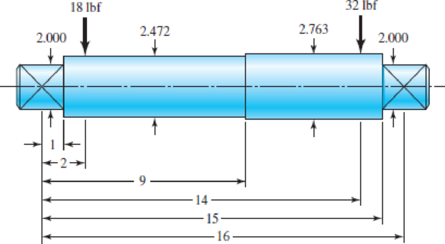
The steel shaft shown in the figure carries a 18-lbf gear on the left and a 32-lbf gear on the right. Estimate the first critical speed due to the loads, the shaft’s critical speed without the loads, and the critical speed of the combination.
Problem 7–32
Dimensions in inches.
The first critical speed of the shaft due to loads.
The critical speed of the shaft without loads.
The critical speed of the combination.
Answer to Problem 32P
The first critical speed of the shaft due to loads is
The critical speed of the shaft without loads is
The critical speed of the combination is
Explanation of Solution
Write the expression for the moment of the inertia.
Here, the diameter of the shaft is
Write the expression for the ratio of the bending moment to inertia.
Here, the bending moment across the shaft is
Write the expression for the ratio of the bending moment to inertia in terms of the spread sheet cell locations.
Substitute
Here, the young’s modulus of the shaft material is
Integrate the Equation (IV) with respect to x.
Substitute
Apply the boundary conditions.
Substitute
Substitute
Substitute
Substitute
Write the expression for the deflection at
Write the expression for the deflection at
Write the expression for the deflection of the shaft due to
Write the expression for the deflection of the shaft due to
Write the expression for the critical velocity due to load.
Here, the acceleration due to gravity is
Write the expression for the weight of the left gear.
Here, the physical constant of the material is
Write the expression for the weight of the right gear.
Write the expression for the critical velocity without load.
Here, the acceleration due to gravity is
Write the expression for the critical speed for the combination using Dunkerley’s equation.
Conclusion:
Draw the diagram for the shaft.
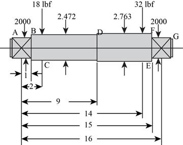
Figure-(1)
The Figure-(1) shows all the dimensions of the shaft.
Calculate the moment of inertia for the part
Substitute
Calculate the moment of inertia for the part
Substitute
Calculate the moment of inertia for the part
Substitute
Since the diameter of the shaft part
Substitute
Substitute
Substitute
Substitute
Substitute
Substitute
Here, the gravitational constant is
Substitute
Thus, he first critical speed of shaft due to loads is
Refer to table A-5 “Physical constants of the materials.” to obtain the weight density of the steel as
Substitute
Substitute
Draw the free body diagram for the calculated weights.
Substitute
Substitute
Substitute
Substitute
Substitute
Substitute
Substitute
Thus, the critical speed of shaft without loads is
Substitute
Thus, the critical speed of the combination is
Want to see more full solutions like this?
Chapter 7 Solutions
Shigley's Mechanical Engineering Design (McGraw-Hill Series in Mechanical Engineering)


- Shaft a in the figure has a power input of 75 kW at a speed of 1000 rev/min in the counterclockwise direction. The gears have a module of 5 mm and a 20° pressure angle. Gear 3 is an idler (b) Find the torque T4c that gear 4 exerts on shaft c.arrow_forwardShaft a in the figure has a power input of 75 kW at a speed of 1000 rev/min in the counterclock-wise direction. The gears have a module of 5 mm and a 20° pressure angle. Gear 3 is an idler.(a) Find the force F3b that gear 3 exerts against shaft b.(b) Find the torque T4c that gear 4 exerts on shaft c.arrow_forward13-31 Shaft a in the figure has a power input of 75 kW at a speed of 1000 rev/min in the counterclock- wise direction. The gears have a module of 5 mm and a 20° pressure angle. Gear 3 is an idler. (a) Find the force F3, that gear 3 exerts against shaft b. (b) Find the torque T4, that gear 4 exerts on shaft c. 517 34T Problem 13-31 3 177arrow_forward
- The shaft in the figure below is part of a drive for an automated transfer system in a metal stamping plant. Gear Q delivers 30 hp to gear B. Sheave D delivers the power to its mating sheave as shown. The shaft carrying B and D rotates at 550 rpm. Use SAE1040 cold drawn steel. Note: Torque on gear at B and the torque on sheave at D are equal. Gear Data: - NB= 96 (Number of teeth on gear B) - Pd= 6 (Diametral pitch for gear B) - Spur gears Gear pressure angle =20o - Shaft at B and D rotate at 550 rpm. Use the following assumptions: - Bearing seats have sharp fillets. Kt=2.5 - Design factor (Factor of Safety) = 3 - Pinion Q is rotating in CCW direction. - Cs= Size factor = 0.80 a) Determine the magnitude of the torque in the shaft at all points b) Compute the forces acting on the shaft at all power-transmitting elements c) Compute the reactions at the bearingsarrow_forwardA pair of straight-tooth bevel gears (as shown in the figure above) are in mesh transmitting 35 hp at 1000 rpm (pinion speed). The gear rotates at 400 rpm. The gear system has a pitch of 6 and a 20-degree pressure angle. The face width is 2 inches and the pinion has 36 teeth. Determine the tangential, radial, and axial forces acting on the pinionarrow_forwardThe four helical gears shown in figure have a module in the normal plane of 4 mm and a pressure angle in the normal plane of 0.35 rad. The motor shaft rotates 550 rpm and transmits 20 kW. Other data are on the drawing. (a) What is the speed ratio between the motor (input) and output shafts? (b) Determine all force components that the 20-tooth pinion applies to the 50-tooth gear. Make a sketch showing these forces applied to the gear. (c) The same as part (b), except for the force components that the 50-tooth gear exerts on the 25- tooth pinion 100 50 teeth 200 125 25 teeth ψ = 0.35 rad right hand Motor 20 teeth ψ = 0.50 rad left hand 50 teeth Outputarrow_forward
- A pinion having 40 teeth drives a gear having 80 teeth. the profile of the gear is involute with pressure angle ( 22), 12 mm module and (14) mm addendum. Find 1-the length of contact2-Arc of contact 3-Contact ratioarrow_forwardProblem 2. A compound gear train as shown in the following figure, Gear 1 has 24 teeth and Gear teeth of diametral pitch of 4. Gear 3 has 30 teeth and Gear 4 has 50 teeth of diametral pitch of 3. Gear 1 turns 12 rpm in clockwise direction. 2 has 70 (a) Computer the speed and direction of the shaft carrying Gear 4. (b) Find the torque at Shaft c if the input horsepower at Shaft a is 50? Shaft b Shaft c Shaft a Gear 1 Gear 2 Gear 3 Gear 4arrow_forwardProblem : A train of spur gears with 20°full-depth involute teeth is shown in the Figure below. Gear 1 is the driving gear and transmits 50 kW power at 300 rpm to the gear train. The number of teeth on gears 1, 2, 3 and 4 are 30, 60, 25 and 50 respectively, while the module for all gears is 8 mm. Gears 2 and 3 are mounted on the same shaft. Gear 1 is rotating in the clockwise direction when seen from the left side of the page. The shaft is made of plain carbon steel 40C8 (Syt = 380 N/mm2) and the factor of safety is 2. Using maximum shear stress theory, estimate suitable diameter of shaft. 150 500 125 3 B1 B2arrow_forward
- In a gear set, a 36-tooth spur pinion drives a 60-tooth spur gear. The teeth of these gear are cast iron profile. The diametral pitch is 6-teeth/in, the face width si 0.5 inches, and the pressure angle is 20 degrees. Assume that the pinion transmits 10 hp at a speed of 2000 rpm. Find the pitch diameters of the gears. Find the pitch line velocity in ft/min Find the velocity factor Ky Find the tangential load in lbf Find the contact stress in kpsi, assuming CP=1960 psi.arrow_forwardA 20 straight-tooth bevel pinion having 14 teeth and a diametral pitch of 4 teeth/in drives a 30-tooth gear. The two shafts are at right angles and in the same plane. The illustration below shows a typical right-angle bevel gear set. Bevel gear pitch diameters are measured on the outside face along the back-cone, as shown in the figure. As shown in figure 13-35, the resultant force acts at the average radius of the gear/pinion. If the power transmitted by the pinion is 10 at 1,453 rpm, calculate the pinion tangent force in lbf. Cone distance A Face Pitch angle Pitch angle Back cone Uniform clearance Pitch diameter Da Back-cone radius, harrow_forwardThe figure shows a pair of shaft-mounted spur gears having a diametral pitch of 5 teeth/in with an 18-tooth 20° pinion driving a 45-tooth gear. The power input is 28-hp at 1700 rev/min. Find the magnitude of the force acting on bearing D. 3 2 3 in 3 in The magnitude of the force acting on bearing Dis lbf.arrow_forward
 Elements Of ElectromagneticsMechanical EngineeringISBN:9780190698614Author:Sadiku, Matthew N. O.Publisher:Oxford University Press
 Mechanics of Materials (10th Edition)Mechanical EngineeringISBN:9780134319650Author:Russell C. HibbelerPublisher:PEARSON
 Thermodynamics: An Engineering ApproachMechanical EngineeringISBN:9781259822674Author:Yunus A. Cengel Dr., Michael A. BolesPublisher:McGraw-Hill Education
 Control Systems EngineeringMechanical EngineeringISBN:9781118170519Author:Norman S. NisePublisher:WILEY
 Mechanics of Materials (MindTap Course List)Mechanical EngineeringISBN:9781337093347Author:Barry J. Goodno, James M. GerePublisher:Cengage Learning
 Engineering Mechanics: StaticsMechanical EngineeringISBN:9781118807330Author:James L. Meriam, L. G. Kraige, J. N. BoltonPublisher:WILEY