
Videos
To provide: The expression of maximum shearing stress as
The constant k for each orientation.
Answer to Problem 53P
The constant k for orientation (a) is
The constant k for orientation (b) is
Explanation of Solution
Given information:
The beam is a hollow square of side a and thickness t.
The beam is subjected to a vertical shear of V.
Calculation:
Orientation (a)
Sketch the cross section of an extruded beam as shown in Figure 1.
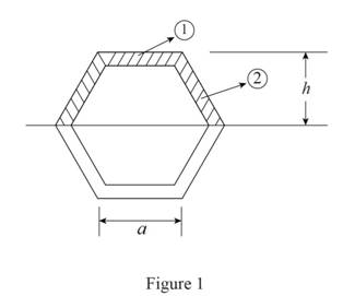
Refer to Figure 1.
The height of the section above neutral axis is
Area of the cross member is
Calculate the area of the member A as shown below.
Calculate the moment of inertia of the beam I as shown below.
Substitute
Calculate the first moment of area as shown below.
Here, A is the area of the section and
Calculate the first moment of area along the neutral axis as shown below.
Substitute
Calculate the shear stress
Here V is the vertical shear.
Substitute
Substitute
Hence, the expression for maximum shearing stress is
Calculate the constant as shown below.
Therefore, the constant k is
(b)
Sketch the cross section of an extruded beam as shown in Figure 2.
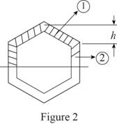
Refer to Figure 2.
The height of the section above neutral axis is
Area of the cross member is
Calculate the area of the member A as shown below.
Calculate the moment of inertia I of the beam as shown below.
Substitute
Calculate the first moment of area as shown below.
Here, A is the area of the section and
Calculate the first moment of area along the neutral axis as shown below.
Substitute
Calculate the shear stress as shown below.
Here V is the vertical shear.
Substitute
Substitute
Hence, the expression for maximum shearing stress is
Calculate the constant as shown below.
Therefore, the constant k is
Want to see more full solutions like this?
Chapter 6 Solutions
Mechanics of Materials, 7th Edition


- Three 1 x 18-in. steel plates are bolted to four L6 x 6 x 1 angles to form a beam with the cross section shown. The bolts have a 78-in. diameter and are spaced longitudinally every 5 in. Knowing that the allowable average shearing stress in the bolts is 12 ksi, determine the largest permissible vertical shear in the beam. (Given: Ix= 6123 in4.)arrow_forwardA square box beam is made of two 3434 × 3.5-in. planks and two 3434 × 5-in. planks nailed together as shown. Know that the spacing between the nails is s = 1.25 in. and that the vertical shear in the beam is V = 260 lb. Determine the maximum shearing stress in the beam.arrow_forwardI need help solving Problem 5.30 5.29) Knowing that P = Q = 480 N, determine (a) the distance a for which the absolute value of the bending moment in the beam is as small as possible, (b) the corresponding maximum normal stress due to bending. (See hint of Prob. 5.27. 5.30) Solve Prob. 5.29, assuming that P = 480 N and Q = 320 N.arrow_forward
- (B) Q: The cantilever beam shown below has a circular cross section of 50mm outer diameter. Portion AB of the beam is hollow, with an inner diameter of 35mm. If the allowable bending stress is 140 MPa, determine (1) the largest allowable uniformly distributed load (w) that can be applied to the beam; (2) the bending stress at a point that is 7 mm below the top of the beam at section D. 50 mm W D B O! 35 mm A - 750 mm 250 mmarrow_forwardA beam carries the loading shown in Fig. 4. Determine, (a) the smallest allowable width b of the beam if the maximum allowable bending stress is 93.75 MN/m². (b) to reduce the weight, a bore was made at the center of the rectangle with a diameter of 60 mm, what is the second moment of area of the resulting shape? 3 m 2 kN/m B www. 9 m Fig. 4 8 kN 3 m D 0000 1 160 mmarrow_forwardA beam having the cross section shown is subjected to a vertical shear V. Determine (a) the horizontal line along which the shearing stress is maximum, (b) the constant k in the following expression for the maximum shearing stress.τmax=k*V/Awhere A is the cross-sectional area of the beamarrow_forward
- Determine (a) the distance a for which the absolute value of the bending moment in the beam is as small as possible, (b) the corresponding moximum normal stress due to bending.arrow_forwardBeam AB is made of three plates glued together and is subjected, in its plane of symmetry, to the loading shown. Knowing that the width of each glued joint is 20 mm, determine the average shearing stress in each joint at section n–n of the beam. The location of the centroid of the section is given in Fig. 1 and the centroidal moment of inertia is known to be I= 8.63 x 10⁻⁶ m4arrow_forwardHomework A timber beam AB of length L and rectangular cross section carries a single concentrated load P at its midpoint C. (a) Show that the ratio Tm/Tm of the maximum values of the shearing and normal stresses in the beam is equal to h/2L, where h and L are, respectively, the depth and the length of the beam. (b) Determine the depth h and the width b of the beam, knowing that L = 2 m, P = 40 kN, 7m = 960 kPa, and om = 12 MPa. |P L/2 - - L/2· A Вarrow_forward
- Homework A timber beam AB of length L and rectangular cross section carries a single concentrated load P at its midpoint C. (a) Show that the ratio Tm/Tm of the maximum values of the shearing and normal stresses in the beam is equal to h/2L, where h and L are, respectively, the depth and the length of the beam. (b) Determine the depth h and the width b of the beam, knowing that L = 2 m, P = 40 KN, T, = 960 kPa, and om = 12 MPa. m · L/2 C - L/2· A Вarrow_forwardThe rigid bar DEF is welded at point D to the steel beam AB. For the loading shown, determine (a) the equations defining the shear and bending at portion AD of the steel beam AB, (b) the location and magnitude of the largest bending moment. (Hint: Replace the 700 N load applied at F by an equivalent force-couple system at D) 750 N/m B D 000 E 2.4 m X 0.9 m 700 N -1.5 m.arrow_forwardQ1. For the beam and loading shown, (a) draw the shear and bending- moment diagrams, (b) determine the equations of the shear and bending-moment curves. 20 kN/m А 3 m 12 m Q2. A steel bar of rectangular cross section is subjected to two equal and opposite counles acting in the vertical plane of symmetry of the bar. Determinearrow_forward
 Elements Of ElectromagneticsMechanical EngineeringISBN:9780190698614Author:Sadiku, Matthew N. O.Publisher:Oxford University Press
 Mechanics of Materials (10th Edition)Mechanical EngineeringISBN:9780134319650Author:Russell C. HibbelerPublisher:PEARSON
 Thermodynamics: An Engineering ApproachMechanical EngineeringISBN:9781259822674Author:Yunus A. Cengel Dr., Michael A. BolesPublisher:McGraw-Hill Education
 Control Systems EngineeringMechanical EngineeringISBN:9781118170519Author:Norman S. NisePublisher:WILEY
 Mechanics of Materials (MindTap Course List)Mechanical EngineeringISBN:9781337093347Author:Barry J. Goodno, James M. GerePublisher:Cengage Learning
 Engineering Mechanics: StaticsMechanical EngineeringISBN:9781118807330Author:James L. Meriam, L. G. Kraige, J. N. BoltonPublisher:WILEY