
International Edition---engineering Mechanics: Statics, 4th Edition
4th Edition
ISBN: 9781305501607
Author: Andrew Pytel And Jaan Kiusalaas
Publisher: CENGAGE L
expand_more
expand_more
format_list_bulleted
Concept explainers
Videos
Textbook Question
Chapter 6, Problem 6.76P
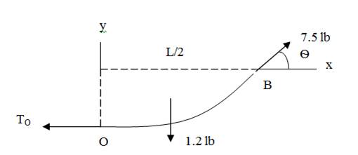
The 50-ft measuring tape weighs 2.4 lb. Compute the span L of the tape to four significant figures.
Expert Solution & Answer
Want to see the full answer?
Check out a sample textbook solution
Students have asked these similar questions
The cross section of the rim of an iron flywheel 3 ft. In diameter is a rectangle 12" by 2". How much does the rim weigh? Note: Iron weighs 450lb/cu ft.
Compute Ix and It for the region shown.
C0nsider the figure bel0w where each square is 1 ft on a side and A =58lb, B =58lb, and C =182lb. Calculate the resultant m0ment of the f0rces (in lb-ft) about point O. (Answer: -690.19lb-ft)
Chapter 6 Solutions
International Edition---engineering Mechanics: Statics, 4th Edition
Ch. 6 - Determine the internal force system acting on...Ch. 6 - Determine the internal force system acting on...Ch. 6 - Determine the internal force system acting on...Ch. 6 - Find the internal force systems acting on sections...Ch. 6 - Find the internal force systems acting on sections...Ch. 6 - Find the internal force systems acting on sections...Ch. 6 - The three identical cantilever beams carry...Ch. 6 - Determine the internal force systems acting on...Ch. 6 - For the structural component shown, determine the...Ch. 6 - Compute the internal force system acting on...
Ch. 6 - Determine the internal force system acting on...Ch. 6 - Determine the internal force systems acting on...Ch. 6 - Determine the internal force systems acting on...Ch. 6 - Find the internal force system acting on section 3...Ch. 6 - The structure is supported by a pin at C and a...Ch. 6 - The 1800lbin. couple is applied to member DEF of...Ch. 6 - A man of weight W climbs a ladder that has been...Ch. 6 - For the ladder in Prob. 6.17, find the internal...Ch. 6 - Determine the internal force system acting on...Ch. 6 - The equation of the parabolic arch is y=(36x2)/6,...Ch. 6 - For the beam shown, derive the expressions for V...Ch. 6 - For the beam shown, derive the expressions for V...Ch. 6 - For the beam shown, derive the expressions for V...Ch. 6 - For the beam shown, derive the expressions for V...Ch. 6 - For the beam shown, derive the expressions for V...Ch. 6 - For the beam shown, derive the expressions for V...Ch. 6 - For the beam shown, derive the expressions for V...Ch. 6 - For the beam shown, derive the expressions for V...Ch. 6 - For the beam shown, derive the expressions for V...Ch. 6 - For the beam shown, derive the expressions for V...Ch. 6 - For the beam shown, derive the expressions for V...Ch. 6 - For the beam shown, derive the expressions for V...Ch. 6 - For the beam shown, derive the expressions for V...Ch. 6 - For the beam shown, derive the expressions for V...Ch. 6 - For the beam shown, derive the expressions for V...Ch. 6 - For the beam shown, derive the expressions for V...Ch. 6 - For the beam shown, derive the expressions for V...Ch. 6 - For the beam shown, derive the expressions for V...Ch. 6 - Derive the shear force and the bending moment as...Ch. 6 - Derive the shear force and the bending moment as...Ch. 6 - The 24-ft timber floor joist is designed to carry...Ch. 6 - For the beam AB shown in Cases 1 and 2, derive and...Ch. 6 - Construct the shear force and bending moment...Ch. 6 - Construct the shear force and bending moment...Ch. 6 - Construct the shear force and bending moment...Ch. 6 - Construct the shear force and bending moment...Ch. 6 - Construct the shear force and bending moment...Ch. 6 - Construct the shear force and bending moment...Ch. 6 - Construct the shear force and bending moment...Ch. 6 - Construct the shear force and bending moment...Ch. 6 - Construct the shear force and bending moment...Ch. 6 - Construct the shear force and bending moment...Ch. 6 - Construct the shear force and bending moment...Ch. 6 - Construct the shear force and bending moment...Ch. 6 - Construct the shear force and bending moment...Ch. 6 - Construct the shear force and bending moment...Ch. 6 - Draw the load and the bending moment diagrams that...Ch. 6 - Draw the load and the bending moment diagrams that...Ch. 6 - Draw the load and the bending moment diagrams that...Ch. 6 - Draw the load and the bending moment diagrams that...Ch. 6 - Draw the load and the bending moment diagrams that...Ch. 6 - Show that the tension acting at a point in a...Ch. 6 - The cable of the suspension bridge spans L=140m...Ch. 6 - The two main cables of the Akashi Kaikyo...Ch. 6 - Cable AB supports the uniformly distributed load...Ch. 6 - A uniform 80-ft pipe that weighs 960 lb is...Ch. 6 - The cable AB supports a uniformly distributed load...Ch. 6 - The string attached to the kite weighs 0.4 oz/ft....Ch. 6 - Show that the tension acting at a point in a...Ch. 6 - A uniform cable weighing 16 N/m is suspended from...Ch. 6 - The tensions in the cable at points O and B are...Ch. 6 - The cable AOB weighs 24 N/m. Determine the sag H...Ch. 6 - The cable of mass 1.8 kg/m is attached to a rigid...Ch. 6 - One end of cable AB is fixed, whereas the other...Ch. 6 - The end of a water hose weighing 0.5 lb/ft is...Ch. 6 - The 50-ft measuring tape weighs 2.4 lb. Compute...Ch. 6 - The cable AOB weighs 5.2 N/m. When the horizontal...Ch. 6 - The chain OA is 25 ft long and weighs 5 lb/ft....Ch. 6 - The 110-lb traffic light is suspended from two...Ch. 6 - The cable carrying 60-lb loads at B and C is held...Ch. 6 - The cable ABCD is held in the position shown by...Ch. 6 - Find the forces in the three cable segments and...Ch. 6 - The cable carrying three 400-lb loads has a sag at...Ch. 6 - The cable supports three 400-lb loads as shown. If...Ch. 6 - Cable ABC of length 5 m supports the force W at B....Ch. 6 - When the 12-kN load and the unknown force P are...Ch. 6 - The cable is loaded by an 80-lb vertical force at...Ch. 6 - The 15-m-long cable supports the loads W1 and W2...Ch. 6 - The cable of length 15 m supports the forces...Ch. 6 - The 14-kN weight is suspended from a small pulley...Ch. 6 - For the cable ABCD determine (a) the angles 2 and...
Knowledge Booster


Learn more about
Need a deep-dive on the concept behind this application? Look no further. Learn more about this topic, mechanical-engineering and related others by exploring similar questions and additional content below.Similar questions
- UPVOTE will be given! Please write the solutions completely and legiby. Box the final answer. Answer in 3 decimal places! Strength of Materials The hook is used to lift the force of P as shown. The section dimensions of a-a is given: P = 40 kN a = 25 mm b = 30 mm c = 70 mm a. Calculate the distance of the centroid of section a-a from the center of curvature in mm. b. Calculate the distance of the neutral axis of section a-a from the center of curvature in mm.arrow_forwardPlease answer all since they are all connected. UPVOTE will be given! Please write the solutions completely and legiby. Box the final answer. Answer in 3 decimal places! Strength of Materials The hook is used to lift the force of P as shown. The section dimensions of a-a is given: P = 40 kN a = 25 mm b = 30 mm c = 70 mm a. Calculate the distance of the centroid of section a-a from the center of curvature in mm. b. Calculate the distance of the neutral axis of section a-a from the center of curvature in mm. c. Calculate the maximum tensile stress in section a-a in MPa. d. Calculate the maximum compressive stress in section a-a in MPa.arrow_forwardFigure (a) shows the cross section of a column that uses a structural shape known as W867 (wide-flange beam, nominally 8 in. deep, weighing 67 lb/ft). The American Institute of Steel Construction Structural Steel Handbook lists the following cross-sectional properties: A=19.7in.2,Ix=272in.4, and Iy=88.6in.4. Determine the dimensions of the rectangle in Fig. (b) that has the same Ix and Iy as a W867 section.arrow_forward
- 25 Find the mass of a cube of edge a, if the density varies as the sum of the distances from three adjacent edges.arrow_forwardSolve for the Maximum Value of P that prevents the bar AB from moving if it weighs 50 Kn pls use 3 decimal places all throughout the solutionarrow_forwardAn L-shaped section has the following dimensions: The length of the longer leg is 5 in, the length of the shorter leg is 31/2., and the thickness of each leg is 3/8 in. The distance y from the back of the shorter leg to the neutral axis XX is A. 1.76 in B. 1.98 in C.1.53 in D. 1.61 inarrow_forward
- b F A F An adjustable plier is shown gripping a circular object, where the geometic dimensions a=0.07 m, b=0.15 m and 0=35 deg. When a force F=34.2 N is applied at the handles as shown, calculate the magnitude of the force (in N) at the pin A (correct to 2 decimal places). Answer:arrow_forward3. In the figure shown, solve for the distance b. 36 kN 20 kN y 2 m 3 m 2 m 94 kN m A 9.arrow_forwardCompute the coordinates of the centroid (, y) of the area shown. d C K a – Values for dimensions on the figure are given in the following table. Note the figure may not be to scale. Variable Value а 47 mm 25 mm 24 mm d 102 mm The x coordinate of the centroid is a = mm. The y coordinate of the centroid is y mm.arrow_forward
- The bar is made from welding two uniform 40 lb bars together. Calculate the magnitude of the pin force at A. Express in pounds and use three significant figures. 8" 24" B 32" Aarrow_forwardthe height of the frame is 50 ftarrow_forwardThe cross sectional dimensions of a beam are shown. If the flange thickness, h, is 12.5 mm, determine the vertical distance from the bottom edge of the flange to the centroid of the cross section. Note: State your answer in mm Note: Do NOT include units in your answer. Answer: ISO HH (20 marrow_forward
arrow_back_ios
SEE MORE QUESTIONS
arrow_forward_ios
Recommended textbooks for you
 International Edition---engineering Mechanics: St...Mechanical EngineeringISBN:9781305501607Author:Andrew Pytel And Jaan KiusalaasPublisher:CENGAGE L
International Edition---engineering Mechanics: St...
Mechanical Engineering
ISBN:9781305501607
Author:Andrew Pytel And Jaan Kiusalaas
Publisher:CENGAGE L
Everything About COMBINED LOADING in 10 Minutes! Mechanics of Materials; Author: Less Boring Lectures;https://www.youtube.com/watch?v=N-PlI900hSg;License: Standard youtube license