
Concept explainers
Videos
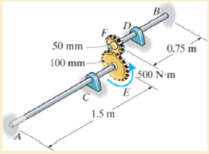
Each has a diameter of 25 mm and they are connected using the gears fixed to their ends. Their other ends are attached to fixed supports at A and B. They are also supported by journal bearings at C and D, which allow free rotation of the shafts along their axes. If a torque of 500 N · m is applied to the gear at E, determine the rotation of this gear.

Trending nowThis is a popular solution!

Chapter 5 Solutions
Mechanics of Materials (10th Edition)
Additional Engineering Textbook Solutions
HEAT+MASS TRANSFER:FUND.+APPL.
Vector Mechanics for Engineers: Statics, 11th Edition
Shigley's Mechanical Engineering Design (McGraw-Hill Series in Mechanical Engineering)
Foundations of Materials Science and Engineering
Thermodynamics: An Engineering Approach
Thinking Like an Engineer: An Active Learning Approach (4th Edition)


- In the gear system shown, the motor applies a torque of 290 N-m to the gear at A. Shaft (1) is a solid 35-mm-diameter shaft, and shaft (2) is a solid 50-mm-diameter shaft. The bearings shown allow free rotation of the shafts. Determine the torque TE provided by the gear system at gear E. B 72 teeth 30 teeth TE (2) E 24 teeth 60 teetharrow_forwardThe gears attached to the A-36 steel shaft are subjected to the torques shown. Determine the angle of twist of end C with respect to end A. The shaft has a diameter of 40 mm. A 0.2 m AAN 300 N·m B 0.5 m GRAA 100 N·m C 200 N·marrow_forwardThe two shafts are made of A-36 steel. Each has a diameter of 25 mm and they are connected using the gears fixed to their ends. Their other ends are attached to fixed supports at A and B. They are also supported by journal bearings at C and D, which allow free rotation of the shafts along their axes. If a torque of 500 N.m is applied to the gear at E as shown, determine the reactions at A and B.arrow_forward
- The shafts are made of steel with shear modulus of 75 GPa. Determine the angle of twist of gear B if a torque of 25 kN·m is applied to gear B. Both shafts have the same diameter of 100 mm. (Hint: for the meshing cylindrical gears, i.e. gear C and D, the angle of twist need to time the radius of the gear while applying the equation of compatibility.)arrow_forwardThe shaft has an outer diameter of 100 mm and an inner diameter of 80 mm. If it is subjected to the three torques, plot the shear stress distribution along a radial line for the cross section within region CD of the shaft. The smooth bearings at A and B do not resist torque.arrow_forward6. Determine the number of 10-mm diameter steel bolts that must be used on the 400-mm bolt circle of the coupling in number 5 to increase the torque capacity to 14 kN-m.arrow_forward
- PROBLEM 1. The shafts are made of A-36 steel and both have 100 mm diameter. If a torque of 60 kN.m is applied to end E and 25 kN.m to the D gear as shown in the figure, determine the angle of twist of the section at E of the DE shaft. 0.75 m 0.75 m 150 mm 25 kN-m 300 mm 60 kN.m 1.25 m Earrow_forwardThe device shown is used to mix soils in order to provide in-situ stabilization. If the mixer is connected to an A-36 steel tubular shaft that has an inner diameter of 3 in. and an outer diameter of 4.5 in., determine the angle oftwist of the shaft at A relative to C if each mixing blade is subjected to the torques shown.arrow_forwardThe solid-circular shafts are connected by gears at B and C as shown below, and having the same diameter (D.). The shear modulus of the shafts is 75 GPa. All bearings allow free rotations of the shafts. Determine the rotation of free end A when a torque T is applied. The values of L1, L2, Do, and T are given in table below. Fixed L1 D 100 mm B 60 mm L2 Student ID 1152179 1155 L2 (mm) (mm) (mm) (N.m) 380 24 L1 Do 38arrow_forward
- The 30-mm-diameter A-36 steel shaft is subjected to the torques shown. Determine the angle of twist of the end B. 30 N-m 200 mm B 600 mm 20 N-m 800 mm 80 N-marrow_forwardThe 60-mm-diameter steel shaft is subjected to the torques shown. Determine the angle of twist of end A with respect to C. Take G = 75 GPa.arrow_forwardDetermine the angle of twist of wheel B with respect to wheel A. The shaft has a diameter of 40 mm and is made of steel for which G = 75 GPa.arrow_forward
 Elements Of ElectromagneticsMechanical EngineeringISBN:9780190698614Author:Sadiku, Matthew N. O.Publisher:Oxford University Press
 Mechanics of Materials (10th Edition)Mechanical EngineeringISBN:9780134319650Author:Russell C. HibbelerPublisher:PEARSON
 Thermodynamics: An Engineering ApproachMechanical EngineeringISBN:9781259822674Author:Yunus A. Cengel Dr., Michael A. BolesPublisher:McGraw-Hill Education
 Control Systems EngineeringMechanical EngineeringISBN:9781118170519Author:Norman S. NisePublisher:WILEY
 Mechanics of Materials (MindTap Course List)Mechanical EngineeringISBN:9781337093347Author:Barry J. Goodno, James M. GerePublisher:Cengage Learning
 Engineering Mechanics: StaticsMechanical EngineeringISBN:9781118807330Author:James L. Meriam, L. G. Kraige, J. N. BoltonPublisher:WILEY