
Videos
5-39* to 5-55* For the problem specified in the table, build upon the results of the original problem to determine the minimum factor of safety for yielding. Use both the maximum-shear-stress theory and the distortion-energy theory, and compare the results. The material is 1018 CD steel.
| Problem Number | Original Problem, Page Number |
| 5-41* | 3-70, 151 |
3-68* to 3-71* A countershaft two V-belt pulleys is shown in the figure. Pulley A receives power from a motor through a belt with the belt tensions shown. The power is transmitted through the shaft and delivered to the belt on pulley B. Assume the belt tension on the loose side at B is 15 percent of the tension on the tight side.
- (a) Determine the tensions in the belt on pulley B, assuming the shaft is running at a constant speed.
- (b) Find the magnitudes of the bearing reaction forces, assuming the bearings act as simple supports.
- (c) Draw shear-force and bending-moment diagrams for the shaft. If needed, make one set for the horizontal plane and another set for the vertical plane.
- (d) At the point of maximum bending moment, determine the bending stress and the torsional shear stress.
- (e) At the point of maximum bending moment, determine the principal stresses and the maximum shear stress.
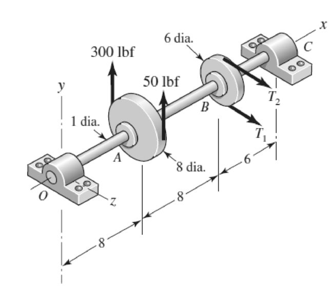
Problem 3-70*
Dimensions in inches.
The factor of safety for yielding from maximum-shear-stress theory.
The factor of safety for yielding from distortion-energy theory.
Answer to Problem 41P
The factor of safety for yielding from maximum-shear-stress theory is
The factor of safety for yielding from distortion-energy theory is
Explanation of Solution
The Free body diagram of pulley
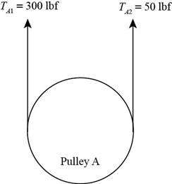
Figure (1)
The free body diagram of pulley
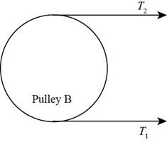
Figure (2)
The tension loose side is
It is given that the belt tension on the loose side at
Write the relationship between tension on the loose side with respect to tension on the tight side.
Here, the tension on the tight side is
Write the equation to balance the tension on the counter shaft.
Here, the tension on the tight side of pulley
Substitute
Calculate the tension on the loose side.
Write the magnitude of bearing reaction force at
Here, the magnitude of the bearing force at
Write the magnitude of bearing reaction force at
Write the magnitude of bearing reaction force at
Here, the magnitude of bearing force at
Write the magnitude of bearing force at
Here, the magnitude of bearing reaction force at
Calculate the bearing reaction force at
Here, the bearing reaction force at
Calculate the bearing reaction force at
Here, the bearing reaction force at
The calculations for shear force and bending moment diagram in
Calculate the shear force at
Here, the shear force at
Calculate the shear force at
Here, the shear force at
Calculate the shear force at
Here, the shear force at
Calculate the moment at
The moment at the supports of the simply supported beam is zero.
Calculate the moment at
Here, the moment at
Calculate the moment at
Here, the moment at
The calculations for shear force and bending moment diagram in
Calculate the shear force at
Here, the shear force at
Calculate the shear force at
Here, the shear force at
Calculate the shear force at
Here, the shear force at
Calculate the moment at
The moment at the supports of the simply supported beam is zero.
Calculate the moment at
Here, the moment at
Calculate the moment at
Write the net moment at
Here, the net moment at
Write the net moment at
Here, the net moment at
Write the torque transmitted by shaft from
Here, the torque transmitted by shaft from
Calculate the bending stress.
Here, the bending stress is
Calculate the shear stress.
Here, the shear stress is
Calculate the maximum principal stress.
Here, the maximum principal stress is
Calculate the minimum principal stress.
Here, the minimum principal stress is
Calculate the maximum shear stress.
Here, maximum shear stress is
Calculate the factor of safety from maximum-shear-stress theory.
Here, the maximum yield stress for
Calculate the factor of safety from distortion-energy theory.
Here, the Von Mises stress is
Write the expression for von Mises stress.
Substitute
Conclusion:
Substitute
Substitute
Substitute
Substitute
Substitute
Substitute
Substitute
Substitute
Substitute
Substitute
Substitute
Substitute
Substitute
Thus, the shear force diagram and bending moment diagram for the shaft in
Figure (4)
Substitute
Substitute
Substitute
Substitute
Substitute
Thus, the shear force diagram and bending moment diagram for the shaft in
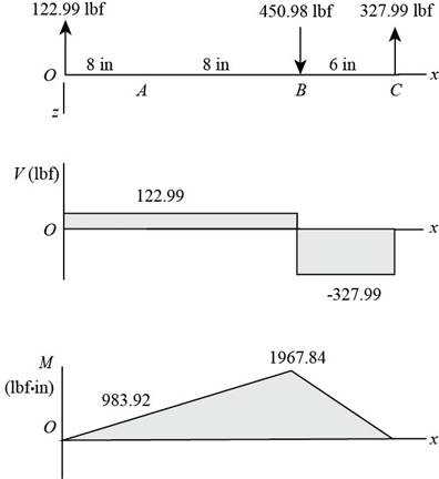
Figure (5)
Substitute
Substitute
Since,
Substitute
Substitute
Substitute
Substitute
Substitute
Substitute
Refer to the Table A-20 “Deterministic ASTM Minimum Tensile and Yield Strengths for Some Hot-Rolled (HR) and Cold-Drawn (CD) Steels” and obtain
Substitute
Thus, the factor of safety for yielding from maximum-shear-stress theory is
Substitute
Thus, the factor of safety for yielding from distortion-energy theory is
Want to see more full solutions like this?
Chapter 5 Solutions
Shigley's Mechanical Engineering Design (McGraw-Hill Series in Mechanical Engineering)


- 6-10 A rotating shaft of 25-mm diameter is simply supported by bearing reaction forces R, and R2. The shaft is loaded with a transverse load of 13 kN as shown in the figure. The shaft is made from AISI 1045 hot-rolled steel. The surface has been machined. Determine (a) the minimum static factor of safety based on yielding. (b) the endurance limit, adjusted as necessary with Marin factors. (c) the minimum fatigue factor of safety based on achieving infinite life. (d) If the fatigue factor of safety is less than 1 (hint: it should be for this problem), then estimate the life of the part in number of rotations.arrow_forward6-28 The figure shows a formed round-wire cantilever spring subjected to a varying force. The hardness tests made on 50 springs gave a minimum hardness of 400 Brinell. It is apparent from the mounting details that there is no stress concentration. A visual inspection of the springs indicates that the surface finish corresponds closely to a hot- rolled finish. Ignore curvature effects on the bending stress. What number of applica- tions is likely to cause failure? Solve using: (a) Goodman criterion. (b) Gerber criterion. = 40 lbf max 12 in- = 20 lbf min Problem 6-28arrow_forward6-25 The cold-drawn AISI 1040 steel bar shown in the figure reversed axial load fluctuating between 28 kN in compression to 28 kN in tension. Estimate the fatigue factor of safety based on achieving infinite life and the yielding factor of safety. If infinite life is not predicted, estimate the number of cycles to failure. 6-mm D. 25 mm Problem 6-25 10 mmarrow_forward
- The plate of the figure is subjected to a bending moment with irregular cycles, which are repeated. In the graphic one of this cycles is represented in terms of stress which appears in each section whose height is h. The piece is made of ductile steel. Determine the number of repetitions of the sequence which the piece can resist before the failure takes place due to fatigue considering a reliability of 95 %. Data: Sult = 1.000 MPa Syp 3D800 Mра thickness e = 4 mm H = 10 cm h = 5 cm r=1 cm ka = 0,72 kp = 0,95 S(MPa) M 400 h 300 200 100 W -100 -200arrow_forwardQ-3 A 25-mm-diameter solid round bar has a groove 2.5-mm deep with a 2.5-mm radius machined into it. The bar is made of AISI 1050 CD steel and is subjected to a purely reversing torque of 250 N-m. For the S-N curve of this material, let f = 0.9. (a) Estimate the number of cycles to failure. (b) If the bar is also placed in an environment with a temperature of 400°C, estimate the number of cycles to failure.arrow_forwardA 1-in-diameter solid round bar has a groove 0.1-in deep with a 0.1-in radius machined into it. The bar is made of AISI 1020 CD steel and is subjected to a purely reversing torque of 1800 lb-in. For the S-N diagram of this material, let f=0.9. Estimate the number of cycles to failure. If the bar is also placed in an environment with a temperature of 750 F, estimate the number of cycles to failurearrow_forward
- 2. The rotating shaft shown in the figure is machined from AISI 1020 CD steel. It is subjected to a force of F= 5.7 kN. Find the minimum factor of safety for fatigue based on infinite life. If the life is not infinite, estimate the number of cycles. Be sure to check for yielding. 25 D.- 20- -20 -35 D. -180- -500- -3 R. 280- (units in mm) -175- -50 D. -25 D. -20 -20arrow_forward8-69 The bolted connection shown in the figure is subjected to a tensile shear load of 90 kN. The bolts are ISO class 5.8 and the material is cold- drawn AISI 1015 steel. Find the factor of safety of the connection for all possible modes of failure. Tarrow_forwardQ-3 A 25-mm-diameter solid round bar has a groove 2.5-mm deep with a 2.5-mm radius machined into it. The bar is made of AISI 1050 CD steel and is subjected to a purely reversing torque of 250 N-m. For the S-N curve of this material, let f= 0.9.arrow_forward
- After recording the applied twisting moment and resulted angle, fill the following table MT (N.m) T. MPa (degree) (rad.) Now, the twisting moment-twisting angle and shear stress-shear strain curves can be plotted, then determine maximum shear stress, shear stress at proportional limit and modulus of rigidity. 4-6 Problem The following torsion test data were obtained for AA6061-T6 aluminum alloy has a round cross section with 30mm outer diameter, 0 inner diameter and 100 length. 0 32 130 Twisted angle (): 0 1 Torque (N.m): 286 347 487 5.5 591 786 910 1105 1163 1235 1222 3.5 6.5 7.5 9. 10.5 13.5 16.5 21.5 25.5 > Plot the torque-twisted angle curve and determine the proportional limit on it. Plot the shear stress-strain curve the determine the shearing strength and modulus of rigidity. Prof. Adnan N. Abood Asst. Lec. Zainah Waheed 25arrow_forwardRequired information This problem illustrates that the factor of safety for a machine element depends on the particular point selected for analysis. Here you are to compute factors of safety, based upon the distortion-energy theory, for stress elements at A and B of the member shown in the figure. This bar is made of AISI 1006 cold-drawn steel and is loaded by the forces F= 0.55 kN, P= 4 kN, and T=25 N-m. Given: Sy= 280 MPa. NOTE: This is a multi-part question. Once an answer is submitted, you will be unable to return to this part. B 15-mm D. -100 mm What is the value of the axial stress at point A? The value of the axial stress at point A is MPa.arrow_forward7-3 The section of shaft shown in the figure is to be designed to approximate relative sizes of d = 0.75D and r = D/20 with diameter d conforming to that of standard rolling- bearing bore sizes. The shaft is to be made of SAE 2340 steel, heat-treated to obtain minimum strengths in the shoulder area of 175 kpsi ultimate tensile strength and 160 kpsi yield strength with a Brinell hardness not less than 370. At the shoulder the shaft is subjected to a completely reversed bending moment of 600 lbf • in, accompaniced by a steady torsion of 400 lbf · in. Use a design factor of 2.5 and size the shaft for an infinite life using the DE-Goodman criterion. Problem 7-3 Section of a shaft containing a grinding-relief groove. Unless otherwise specified, the diameter at the root of the groove d, =d - 2r, and though the section of diameter d is ground, the root of the groove is still a machined surface.arrow_forward
 Mechanics of Materials (MindTap Course List)Mechanical EngineeringISBN:9781337093347Author:Barry J. Goodno, James M. GerePublisher:Cengage Learning