
Applied Statics and Strength of Materials (6th Edition)
6th Edition
ISBN: 9780133840544
Author: George F. Limbrunner, Craig D'Allaird, Leonard Spiegel
Publisher: PEARSON
expand_more
expand_more
format_list_bulleted
Concept explainers
Videos
Textbook Question
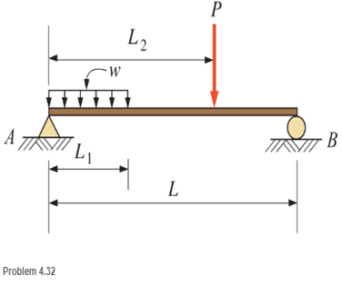
Chapter 4, Problem 4.32CP
For the following computer problems, any appropriate software may be used. Input prompts should fully explain what required of the user (the program should be user-friendly). The resulting output should be well labeled and self-explanatory.
4.32 Write a program that will calculate the reactions for the beam show. User input is to be L, L1, L2, P, and w. Neglect the weight of the beam.
Expert Solution & Answer
Want to see the full answer?
Check out a sample textbook solution
Students have asked these similar questions
5. Draw complete, clearly labeled free-body diagrams. All unknown support reactions should be clearly labeled with a variable name. All known values such as weight or applied forces should be clearly labeled with their known values.
Don't need to show equilibrium equations, I just need free-body diagrams. Only solve this text question, not the questions in image.
The tension is growing!Context
At your summer job, your supervisor wants to test your physics skills. A new winch (a cable driven by a motor) is to be used to hoist loads up an inclined ramp. Your supervisor is worried about the packages arriving too quickly at the top of the ramp.
Constraints
The inclined ramp is made up of small cylinders that are free to rotate: there is no friction between the ramp and the load.The angle theta of the ramp from the horizontal is known.The winch cable exerts a known force.The cable is oriented at an angle a from the horizontal.The charge, initially immobile, has a known mass.The length of the ramp is known.
Schematization
Draw a diagram of the object that interests us. Draw your x and y axes. Draw and name each force experienced by the object that interests us.
Modelization
Build a model to calculate the final speed of the load as it arrives at the top of the ramp, given the known parameters. Then test your model with the following values:
Ramp…
Free body diagram
Draw the free body diagram (FBD) for this system. To draw the free body diagram, we assume that the bar is displaced a small amount in the positive
direction of 0. Important: For the free body diagram, the forces also need to be labelled! You can draw the forces by clicking the application point
(letters) and dragging or using the drop down with the 'draw' button. If you drew them by clicking and dragging, click the force vector to label it from the
dropdown menu above. If the label on the force doesn't appear on the diagram, you haven't quite done it right and the question will keep getting graded as
incorrect even if you have the correct arrows.
Fs
k2
Fry
Fg
k1
Frx
Equation of Motion
Since the bar undergoes rotational motion, Newton's second law is written by writing a sum of moments around the pivot point (sum of moments cause
rotational motion). Positive moments are those that are in the direction that tend to move things in what is defined as the positive…
Chapter 4 Solutions
Applied Statics and Strength of Materials (6th Edition)
Ch. 4 - and 4.2 Sketch free-body diagram for the members...Ch. 4 - Sketch free-body diagram for the members shown.Ch. 4 - A steel cylinder having a mass of 120 kgis...Ch. 4 - A 50-lb block is supported by a pin support and a...Ch. 4 - A cylinder weighing 200 lb is supported on an...Ch. 4 - A weight W is supported by a flexible cable and an...Ch. 4 - The ladder shown is supported by a smooth...Ch. 4 - What horizontal force F applied at the center of...Ch. 4 - Calculate the force in cable AB and the angle (...Ch. 4 - Calculate the horizontal force F that should be...
Ch. 4 - Calculate the reactions of the two smooth inclined...Ch. 4 - Calculate the force in each cable for the...Ch. 4 - Three members of a truss intersect at joint B as...Ch. 4 - Four concurrent forces in equilibrium act at point...Ch. 4 - The beam shown carries vertical concentrated...Ch. 4 - Find the reactions at A and B for the beam shown....Ch. 4 - A simply supported beam spans 10 m. The beam...Ch. 4 - The beam shown carries vertical loads. Calculate...Ch. 4 - Calculate the reaction at each support for the...Ch. 4 - Calculate the reactions at A and B for the beam...Ch. 4 - Calculate the reactions at A and B for the beam...Ch. 4 - A 12-ft simple beam is supported at each end. It...Ch. 4 - The beam shown carries vertical loads as...Ch. 4 - Determine the reactions for the beam shown. The...Ch. 4 - Calculate the reaction at each support for the...Ch. 4 - Calculate the wall reactions for the cantilever...Ch. 4 - Determine the reactions at supports A and B of the...Ch. 4 - A mass M of 300 kg is supported by a boom, as...Ch. 4 - Rework Problem 4.28 assuming that point D has been...Ch. 4 - Calculate the force in the tie rod BC and the...Ch. 4 - The davit shown is used in pairs for...Ch. 4 - For the following computer problems, any...Ch. 4 - For the following computer problems, any...Ch. 4 - For the following computer problems, any...Ch. 4 - For the structure shown, draw free-body diagram...Ch. 4 - A 1200-lb load is supported by a cable that runs...Ch. 4 - For the pin-connected frame shown, sketch a...Ch. 4 - For the concurrent force system shown, calculate...Ch. 4 - A strut having a mass of 40 kg/m is supported by a...Ch. 4 - Calculate the reaction at each support for the...Ch. 4 - Calculate the reaction at each support for the...Ch. 4 - A beam supports a nonuniformly distributed load as...Ch. 4 - Calculate the reactions at each support for the...Ch. 4 - Compute reactions at each support for the beam...Ch. 4 - A rod of uniform cross section weighs 4 lb/ft and...Ch. 4 - A 12-ft-long weightiness member supports two...Ch. 4 - A uniform rod AB, having a weight of 5.00 lb and a...Ch. 4 - The plastic barrel tent anchor of Problem 2.11...Ch. 4 - Compute the reactions at A and B for the bracket...Ch. 4 - The truss shown is supported by a pin at A and a...Ch. 4 - Find the reactions at supports A and B for the...Ch. 4 - Find the reactions at supports A and B for the...Ch. 4 - Determine the reactions at A and B for the truss...Ch. 4 - A 40-ft ladder weighing 130 lb is pin-connected to...Ch. 4 - The frame shown is pin-connected at point A and...Ch. 4 - Prob. 4.56SPCh. 4 - A horizontal beam is pin-connected to a wall at...Ch. 4 - Calculate the force in the cable for the structure...Ch. 4 - The Thenard shutter dam shown was originally...Ch. 4 - An inclined railway can be used to lift heavy...Ch. 4 - Two cylinders are supported in a box, as shown....
Knowledge Booster


Learn more about
Need a deep-dive on the concept behind this application? Look no further. Learn more about this topic, mechanical-engineering and related others by exploring similar questions and additional content below.Similar questions
- 8.5.2 Represent and reason y PIVOTAL Class: Equipment per group: whiteboard and markers. Iupe on beam sope on beam 2 ton beam (200 N) „ (600 N) 10 m 7 m 5 m person on beam A force diagram for a beam is shown at the right. Help your group members to apply the first and second conditions of equilibrium for this situation and solve for the unknown forces. Draw a picture of a situation that the diagram might describe. Put your work on a whiteboard.arrow_forwardA truss is facing a two-force member and both of them are in the opposite directions, and the truss is in equilibrium. And both of them are coming to each other. The forces are called Select one: O a. Tensile Forces O b. Compressive forces O c Parallel and collinear forces with same direction of heading O d. The rotational forces Next page est-3 Jump to...arrow_forwardLearning Goal: To analyze a rod assembly in three-dimensional space and determine the support reactions by using the equations of equilibrium for a rigid body. The rod assembly shown has smooth joumal bearings at A, B, and C. The forces F 600 N. F-480 N. F 460 N, and F-900 N are applied as shown in the figure. The geometry of the rod assembly is given as a 0.900 m, &0.650 m, and c 0.800 m Neglect the weight of the rod Determine the magnitude of the 2 component of the reaction on the rod at A Express your answer to three significant figures and include the appropriate units. View Available Hint(s) Submit PA A₁ = Value Submit Part F- Finding the x component of the reaction at A Determine the magnitude of the x component of the reaction on the rod at A Express your answer to three significant figures and include the appropriate units. View Available Hint(s) Units μÁ Value ? Units ?arrow_forward
- 4. Sit in your chair with your arms at your side. Raise one arm out to your side so it is abducted 45 degrees. Hold for 30 seconds. Relax. Then raise the same arm again so it is abducted to 90 degrees. Hold for 30 seconds. Relax. Then raise the arm so it is abducted to 120 degrees. Answer the following questions. A. Draw a free body diagram to represent each of the three conditions.arrow_forwardThree forces act on particle A located at the origin of an x-y coordinate system. Force B acts at 140o from the positive x-axis, and force C acts at 15o from the positive x-axis. The weight acts down with a magnitude of W = 100 kN. Use the equations of equilibrium to determine the magnitudes of B and C such that particle A is in equilibrium. Carefully draw a neat, labeled, free body diagram of particle C. Based on your FBD develop two equilibrium equations in terms of the symbols defined on your free body diagram. Find angles α and β. FB= 117.92 kn Fc= 93.507 Knarrow_forwardFind the reactions. Fill in the blank'sarrow_forward
- A weight W= 120 kN is being supported by steel sections with force T, force F, andforce C. The coordinates of A, B, C, and D are given. Assume that E is the origin(0,0,0). Determine Forces T, F, and C. (Hint: Produce three equations fromequilibrium of force system)Note: The Forces T, F, and C must be computed accurately to design the proper sizes ofsteel sections in the subject “Steel Design.”arrow_forwardYou are driving on the highway, and you come to a steep downhill section. As you roll down the hill, you take your foot off the gas pedal. You can ignore friction, but you can't ignore air resistance. Draw a free-body diagram of the car. Draw the force vectors with their tails at the dot. The orientation of your vectors will be graded. The exact length of your vectors will not be graded. 0 No elements selected w Select the elements from the list and add them to the canvas setting the appropriate attributes.arrow_forward3. Two people carry a heavy electric motor by placing it on a light board 2.00 m in length. One person lifts at one end with a force of 70ON, and the other lifts the opposite end with a force of 500N. What is the weight of the motor, and where along the board is its center of gravity located? (Note: The center of gravity of an object is the point where the weight passes through.)arrow_forward
- Using the node method and using matrices in Matlab, determine the force on each element of the armature shown in the following figure. Set whether the elements are in tension or in compression. Also calculate the reactions in the supports. Number the nodes and the elements and pose the sum of forces in X and Y in each of the nodes, including the supports. To propose the equations consider that all the elements are in tension (positive value), if the result is negative it means that they are in compression. The same with the reactions. The unknowns are the forces in the elements and the reactions, the known values are the applied loads. 6-6. Determine the force on each element of the weapon-lasts and establish whether the elements are in tension or in compression. Consider P1 = 2 KN and P2 = 1.5 KN. 30° 3 m P₁ 30° 3 marrow_forwardQ/ Find the reaction Force of system in A,B,C Shown in figarrow_forwardsolve equilibriumarrow_forward
arrow_back_ios
SEE MORE QUESTIONS
arrow_forward_ios
Recommended textbooks for you
 Elements Of ElectromagneticsMechanical EngineeringISBN:9780190698614Author:Sadiku, Matthew N. O.Publisher:Oxford University Press
 Mechanics of Materials (10th Edition)Mechanical EngineeringISBN:9780134319650Author:Russell C. HibbelerPublisher:PEARSON
 Thermodynamics: An Engineering ApproachMechanical EngineeringISBN:9781259822674Author:Yunus A. Cengel Dr., Michael A. BolesPublisher:McGraw-Hill Education
 Control Systems EngineeringMechanical EngineeringISBN:9781118170519Author:Norman S. NisePublisher:WILEY
 Mechanics of Materials (MindTap Course List)Mechanical EngineeringISBN:9781337093347Author:Barry J. Goodno, James M. GerePublisher:Cengage Learning
 Engineering Mechanics: StaticsMechanical EngineeringISBN:9781118807330Author:James L. Meriam, L. G. Kraige, J. N. BoltonPublisher:WILEY
Elements Of Electromagnetics
Mechanical Engineering
ISBN:9780190698614
Author:Sadiku, Matthew N. O.
Publisher:Oxford University Press
Mechanics of Materials (10th Edition)
Mechanical Engineering
ISBN:9780134319650
Author:Russell C. Hibbeler
Publisher:PEARSON
Thermodynamics: An Engineering Approach
Mechanical Engineering
ISBN:9781259822674
Author:Yunus A. Cengel Dr., Michael A. Boles
Publisher:McGraw-Hill Education
Control Systems Engineering
Mechanical Engineering
ISBN:9781118170519
Author:Norman S. Nise
Publisher:WILEY
Mechanics of Materials (MindTap Course List)
Mechanical Engineering
ISBN:9781337093347
Author:Barry J. Goodno, James M. Gere
Publisher:Cengage Learning
Engineering Mechanics: Statics
Mechanical Engineering
ISBN:9781118807330
Author:James L. Meriam, L. G. Kraige, J. N. Bolton
Publisher:WILEY
Types Of loads - Engineering Mechanics | Abhishek Explained; Author: Prime Course;https://www.youtube.com/watch?v=4JVoL9wb5yM;License: Standard YouTube License, CC-BY