
Concept explainers
Videos
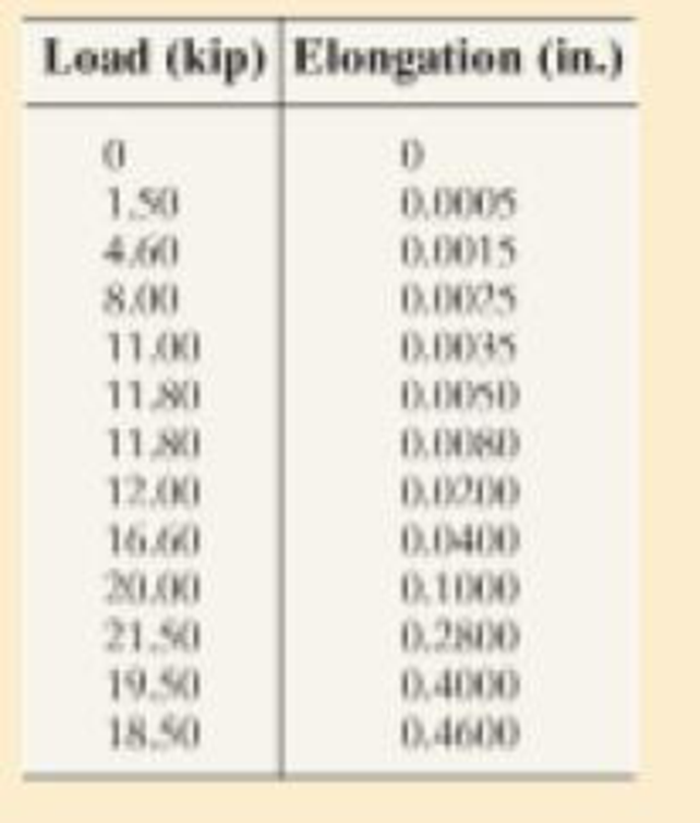
A tension test was performed on a steel specimen having an original diameter of 0.503 in. and gage length of 2.00 in. The data is listed in the table. Plot the stress-strain diagram and determine approximately the modulus of elasticity, the yield stress, the ultimate stress, and the fracture stress. Use a scale of 1 in. = 20 ksi and 1 in. = 0.05 in./in. Redraw the elastic region, using the same stress scale but a strain scale of 1 in. = 0.001 in./in.
Prob. 3–1
Want to see the full answer?
Check out a sample textbook solution
Chapter 3 Solutions
Mechanics of Materials (10th Edition)
Additional Engineering Textbook Solutions
Applied Fluid Mechanics (7th Edition)
Automotive Technology: Principles, Diagnosis, And Service (6th Edition) (halderman Automotive Series)
Statics and Mechanics of Materials (5th Edition)
Engineering Mechanics: Statics & Dynamics (14th Edition)
Automotive Technology: Principles, Diagnosis, and Service (5th Edition)
Engineering Mechanics: Dynamics (14th Edition)


- a 200mm long rod with a diameter of 50mm is loaded with a 4kN weight.the rod finale length 201.314mm and finale diameter 42mm.the load at the fracture is 2.5kN and the maximum load is 3.5kN. Calculate to third decimal and determine the folliwing 1.stress 2.strain 3.limit of proportionality 4.percentage of reduction in area 5.percentage elogationarrow_forwardThe stress-strain diagram for an aluminum alloy specimen having an original diameter of 0.5 in. and a gauge length of 2 in. is given in the figure. If the specimen is loaded until it is stressed to 60 ksi, determine the approximate amount of elastic recovery and the increase in the gage length after it is unloaded.arrow_forwardThe stress–strain diagram for a steel alloy having an original diameter of 0.5 in. and a gage length of 2 in. is given in the figure. If the specimen is loaded until it is stressed to 70 ksi, determine the approximate amount of elasticrecovery and the increase in the gage length after it is unloaded.arrow_forward
- The stress-strain diagram of a reinforcement steel having a cross-sectional diameter of 12 mm diameter and 100 mm gage length is determined after its tensile strength test as follows. Based on the stressstrain diagram determine the followings properties of the material (Poisson’s ratio of the material is 0.32) :arrow_forwardIn a standard tensile test a steel rod of 7/8 in. in diameter is subjected to a tension force of 17 kips. Determine the ratio of the shear modulus to the modulus of elasticity of a material whose Poisson's ratio is 0.25.arrow_forward39) A tensile test specimen has a gauge length=2in. and a diameter of 0.875in. Yielding occurs at a load of 35,500lbs. The corresponding gauge length = 2.0113in. (neglect the .2% yield point). The maximum load of 45,000lbs is reached at a gauge length of 2.543in. If fracture occurs at a gauge length of 2.673in, determine the percent elongation at fracture (Round to the nearest whole %)arrow_forward
- A rosette consisting of 3 gages forming, respectively, angles of θa, θb and θc with the x-axis is attached to the free surface of machine components made of material with a given Poisson’s ratio v and Modulus of elasticity E as shown in Fig. 6. Take note that strain values given above are the gage readings and not principal strains. PLEASE ANSWER I,G,Harrow_forwardThe strain value of the structure in the same direction as a result of the pull applied in the X axis from the bottom was measured as 0.26 mm / mm. Under the same loading condition: a) Calculate the strain on the Z axis of the structure. b) In this case, what is the strain type of the structure in the Z axis?arrow_forwardTo determine the nominal or engineering stress and strain experienced by a specimen of a material while it is subjected to a tension test, and to be able to read important values from a conventional stress-strain diagram obtained from the test. A tension test is being conducted on a steel-rod specimen with a gauge length of L0=50 mm and initial diameter of d0=13 mm. Data were collected to form the conventional stress-strain diagram as shown. From the diagram, f = 506 MPa , e = 689 MPa , g = 585 MPa , and h = 0.146 mm/mm . A) Assuming that the strain remains constant throughout the region between the gauge points, determine the nominal strain ε experienced by the rod if it is elongated to L = 53.0 mm . B) Assuming that the stress is constant over the cross-sectional area and if the tension force used is P = 16.0 kN , find the nominal stress experienced by the rod. C)Determine the force P needed to reach the ultimate stress in the steel-rod specimen.arrow_forward
- It is used to find the shear strength of a 3-system material. T-shaped test is used for this. When driving in the way, t = 4mm, bottom wide is 10 mm and T section is 15 mma) Find the shear strength of the specimen as shear damage occurs when a force of F9 kN is applied to the specimen.b) Calculate the maximum normal stress occurring in the sample when a force of F = 9 kN is applied.arrow_forwardThe stress-strain diagram for a steel alloy having an original diameter of 0.5 in. and a gauge length of 2 in. is given in the figure. Determine approximately the modulus of elasticity for the material, the load on the specimen that causes yielding, and the ultimate load the specimen will support.arrow_forwardThe following data (in given figure) were obtained from the tensile test of Aluminum alloy. The initial diameter of test specimen was 0.505 inch and gauge length was 2.0 inch. Plot the stress strain diagram and determine(a) Proportional Limit (b) Modulus of Elasticity (c) Yield Stress at 0.2% offset (d) Ultimate Stress and(e) Nominal Rupture Stress.arrow_forward
 Elements Of ElectromagneticsMechanical EngineeringISBN:9780190698614Author:Sadiku, Matthew N. O.Publisher:Oxford University Press
 Mechanics of Materials (10th Edition)Mechanical EngineeringISBN:9780134319650Author:Russell C. HibbelerPublisher:PEARSON
 Thermodynamics: An Engineering ApproachMechanical EngineeringISBN:9781259822674Author:Yunus A. Cengel Dr., Michael A. BolesPublisher:McGraw-Hill Education
 Control Systems EngineeringMechanical EngineeringISBN:9781118170519Author:Norman S. NisePublisher:WILEY
 Mechanics of Materials (MindTap Course List)Mechanical EngineeringISBN:9781337093347Author:Barry J. Goodno, James M. GerePublisher:Cengage Learning
 Engineering Mechanics: StaticsMechanical EngineeringISBN:9781118807330Author:James L. Meriam, L. G. Kraige, J. N. BoltonPublisher:WILEY