
Videos
An oil pipeline and a 1.3-m3 rigid air tank are connected to each other by a manometer, as shown in Fig. P3-146. If the tank contains 15 kg of air at 80
(a)
The absolute pressure in the pipeline.
Answer to Problem 146P
The absolute pressure in the pipeline is
Explanation of Solution
Given information:
Volume rigid air tank is
Write the expression for absolute pressure of air in the tank.
Here, the mass of air in the tank is
Write the expression for absolute pressure in the pipeline.
Here, specific gravity of oil is
Calculation:
Substitute
Substitute
Conclusion:
The absolute pressure in the pipeline is
(b)
The change in
Answer to Problem 146P
The change in
Explanation of Solution
Given information:
Temperature of air in the tank is
The figure below shows the new schematic diagram of manometer.
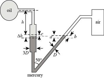
Figure-(2)
Write the expression for absolute pressure of air in the tank.
Here, the mass of air in the tank is
Write the expression for equation of balancing the volumes in both arms of the manometer.
Here, the diameter of limb is
Write the expression for vertical height corresponding to
Substitute
Write the expression for equation of pressure head balance in manometer.
Substitute
Calculation:
Substitute
Substitute
Conclusion:
The change in
Want to see more full solutions like this?
Chapter 3 Solutions
Fluid Mechanics: Fundamentals and Applications
Additional Engineering Textbook Solutions
Mechanics of Materials, 7th Edition
Introduction To Finite Element Analysis And Design
Introduction to Heat Transfer
Thermodynamics: An Engineering Approach
Vector Mechanics for Engineers: Statics, 11th Edition
Thermodynamics: An Engineering Approach


- (b) Consider two identical water tanks (20 m x 10 m x 10 m) filled with water. The depth of water in the first tank is 8 m and it is stationary. The depth of water in the second tank is 6 m and it is moving vertically downward with a constant acceleration of 3.3 m/s?. Which tank will have a higher pressure at the bottom? Now, the first tank is moving horizontally in the direction of its length with a constant acceleration of 2.4 m/s?. Determine the shape of the free surface and the total force on the base and vertical faces of this tank. What will happen if these tanks are completely filled with water?arrow_forwardPgage U-shaped liquid manometer is connected to a closed tank, which contains water and air. The gage pressure in the tank is Pagge = 30 kPa. The manometric fluid is mercury, with density pmercury = 13600 kg/m³, and the water density is Pwater 1000 kg/m³. Determine the readings of the liquid manometer (h = ?), as shown on the figure, if the specific weight of the air is neglected. Air Im Water Im Im %3D h Mercuryarrow_forwardA multifluid container is connected to a U-tube, as shown in the figure. For the given specific gravitles and fluid column heights. determine the gage pressure at A. Also determine the height of a mercury column that would create the same pressure at A. The column heighth of oil is 86 cm. The specific gravitles are 1.26 for glycerin and 0.90 for oll. We take the standard density of water to be Pw=1000 kg/m³ and the specific gravity of mercury to be 13.6. h 35 cm 18 cm Į Oil SG-0.90 Water Glycerin SG-1.26 90 cm 15 cm The gage pressure at A is kPa. The height of a mercury column that would create the same pressure at A is cm.arrow_forward
- The water in a tank is pressurized by air, and the pressure is measured by a multi-fluid manometer, as shown in the figure. Determine the gage pressure of air in the tank.arrow_forwardConsider a double-fluid manometer as shown in the figure, attached to an air tank. If one fluid is mercury, determine the density of the other fluid for the given pressure. Take Patm= 100 kPa.arrow_forwardPipe A contains gasoline (SG = 0.7), pipe B contains oil (SG = 0.9), and the manometer fluid is ,ercury. Determine the new differential reading if the pressure in pipe A is decreased 25 kPa, and the pressure in pipe B remains constant. The initial differential reading is 0.30 m. (Hydrostatic)arrow_forward
- A force, P, is applied to a piston with a mass of 15 kg and a diameter of 43 cm that rests on top of a cylinder containing water as shown. (The piston is free to move in the cylinder, but is sealed so no water can escape.) An open U-tube manometer is connected to the cylinder as shown. Determine the applied force, P in kN, if h1 = 68 mm and h = 100 mm. You can use the following data: the specific weight of water is 9.81 kN/m³ and the specific gravity of mercury is 13.546. Approximate your answer to three decimal places TU Piston Water Mercuryarrow_forwardConsider a U-tube manometer used to measure the density Pa of liquid A, as shown below. Mercury is used as the base liquid for the manometer with density Phg = 13600kg/m³. If hng = 5mm and ha = 22.4 mm, find Pa. ha Pa U Phg hngarrow_forwardthe gauge pressure of the air in the tank is shown in Fig. p3-49 is measured to be 65 kPa. Determine the differential height H of the mercury column.arrow_forward
- The helium-filled blimp shown in the figure below is used at various athletic events. Determine the number of pounds of helium (lbm) within it if its volume is 68,000 ft3 and the temperature and pressure are 80 °F and 14.2 psia, respectively. The gas constant for helium is 1.242×10⁴ (ft-lbf)/(slug-R).arrow_forwardAs shown in the figure, an inclined manometer is used to measure the pressure of the gas within the reservoir. The manometer fluid is mercury, which has a density of 845 lb/ft³. The manometer fluid risera distance d = 7 inches along the manometer tube, which is inclined 0 = 20° from the horizontal. The atmospheric pressure is 14.7 lbf/in² and the acceleration of gravity is 32.2 ft/s². Gas reservoir B Mercury (p = 845 lb/ft³) Determine the gas pressure, in lbf/in². Express the pressure as a gage or a vacuum pressure, as appropriate, in lbf/in². Patm = 14.7 lbf/in.² g=32.2 ft/s² 20 in.arrow_forwardA 3-m-diameter, 7-m-long cylindrical tank is completely filled with water. The tank is pulled by a truck on a level road with the 7-m-long axis being horizontal. Determine the pressure difference between the front and back ends of the tank along a horizontal line when the truck (a) accelerates at 3 m/s2 and (b) decelerates at 4 m/s2.arrow_forward
 International Edition---engineering Mechanics: St...Mechanical EngineeringISBN:9781305501607Author:Andrew Pytel And Jaan KiusalaasPublisher:CENGAGE L