
Videos
Describe the behavior of the bulb in the two situations below.
i. The switch is first moved to position 1. Describe the behavior of the bulb from just after the switch is closed until a long time later. Explain.
ii. The switch is now moved to position 2. Describe the behavior of the bulb from just after the switch is closed until a long time later. Explain your reasoning.
(i)
The behavior of the bulb from just after the switch is closed until a long time later in the situation when the switch is first moved to position
Explanation of Solution
Introduction:
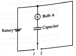
Consider the circuit shown in Figure 1.
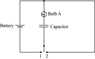
Figure 1
The brightness of the bulb depends upon the current flowing through that bulb. The bulb will be brighter if the flow of current through that bulb is high. In other words, more current passes through less resistance that mean if the resistance is less then bulb will appear brighter.
The circuit diagram when the switch is at position
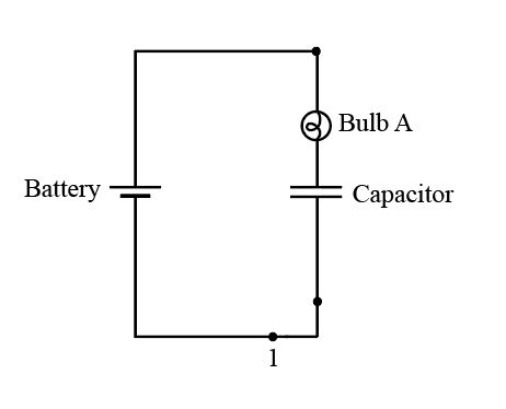
Figure 2
Initially, thecapacitor is short circuited and starts charging slowly. As thecurrent decays with respect to time, the bulb initially glows, but later it goes dimmer with time, and after a long time it stops glowing.
If it stops glowing, the capacitor comes in the open circuit condition and the current flow across it is zero.
Conclusion:
Therefore, the behavior of the bulb from just after the switch is closed until a long time later is described above.
(ii)
The behavior of the bulb from just after the switch is closed until a long time later in the situation when the switch is now moved to position
Explanation of Solution
Introduction:
The brightness of the bulb depends upon the current flowing through that bulb. The bulb will be brighter if the flow of current through that bulb is high. In other words, more current passes through less resistance that mean if the resistance is less then bulb will appear brighter.
The circuit diagram when the switch is at position
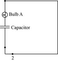
Figure 3
The capacitor voltage is equal to battery voltage at the initial stage.After this, capacitor startsdischarging and the currentdecays with time. So, blub glows bright initially, but thengoes dimmer with time, and after long timeit stops glowing.
If it stops glowing, the capacitor comes in the open circuit condition and the current flow across it is zero.
Conclusion:
Therefore, the behavior of the bulb from just after the switch is closed until a long time later is described above.
Want to see more full solutions like this?
Chapter 20 Solutions
Tutorials in Introductory Physics
Additional Science Textbook Solutions
Physics (5th Edition)
Physics for Scientists and Engineers: A Strategic Approach, Vol. 1 (Chs 1-21) (4th Edition)
College Physics (10th Edition)
Modern Physics
Essential University Physics: Volume 2 (3rd Edition)
Essential University Physics (3rd Edition)


- Consider the circuit diagram depicted in the figure. Part (a) If the current through the top branch is I2 = 0.025 A, what is the current through the bottom, I3, in amps?arrow_forwardA triangular array of resistors is shown in the figure on the right. What current will this array draw from a 35.0V battery having negligible internal resistance if we connect it across a.) ab; b.) bc and c.) ac?arrow_forwardGood afternoon! I am working on problem number 26 in the attached pic. I also sent a pic of where I am getting hung up. If you guys could help me understand what to do next and perhaps give a short explanation as to why, I would greatly appreciate it! Thanks in advance:-)arrow_forward
- I keep getting different answers with each calculation and unsure of where I am going wrong. If possible, please show steps so I may understand where my calculations were incorrect. (a). What's the capacitance of your capacitor? (the value and unit(s)). (b). If you disconnect the battery and separate the plates to a distance of 3.50 cm without discharging them, what will be the potential difference between them? (the value and unit(s)).arrow_forwardIf the EMF is 12 V, then determine the following. (a) What is the equivalent resistance of the circuit in the diagram? (b) What is the voltage across the 4.0 Ω resistor? (c) What is the current in the 3.0 Ω resistor? (d) Show your steps in the process of reducing the circuit.arrow_forwardIdentical bulbs are shown in the circuit. 1) Is bulb A brighter, dimmer, or the same brightness as bulb B? Explain 2) Is the current through bulb D greater that or less that, or equal to the current through bulb F. Explain. 3) If bulb F is unscrewed from its socket, does bulb B become brighter, dimmer, or stay the same. Explain.arrow_forward
- 1. What is the time constant of the circuit formed when a and c are connected? Give your answer in ms to 3 significant digits. 2. What is the time constant of the circuit formed when b and c connected? Give your answer in ms to 3 significant digits. 3. You perform the following sequence of events. The capacitor starts uncharged and the switch is flipped to connect a and c. The capacitor is charged for 20 ms. The switch is then flipped to connect b and c, and the capacitor is discharged for 26 ms, at which time the switch is set to the position where it is not in contact with either a or b. What is the voltage on the capacitor? Give your answer to 2 significant digits.arrow_forwardConsider the circuit configurations below, where two lightbulbs are connected to a single battery in different ways. Based on what you learned about parallel and series connections in lab, which of these two configurations would result in the light bulbs being the brightest? Fully explain your reasoning. Imagine that you are given four 100Ω resistors to build a circuit. Your challenge is to use all four of the resistors in the circuit, but the circuit must have an overall equivalent resistance of 100Ω. Is this possible? If so, draw a diagram of the circuit and explain how the connections result in a 100Ω equivalent resistance. If this is not possible, draw a diagram of a circuit involving all four resistors that has an equivalent resistance as close to 100Ω as is possible.arrow_forwardThree resistors having resistances of 4.0 Ω, 6.0 Ω, and 10.0 Ω are now connected in series. If the combination is connected to an ideal 12-V. What is the total resistance of the circuit? What is the current through each resistor? What is the voltage drop across each resistor? What is the power dissipated by the 6.0 Ω resistor? Clearly state the formulae you’re using and what your letters/symbols mean.arrow_forward
- Part A through D please and thank youNow combining all capacitors in problem 5, you come up with a circuit with one battery, one resistor, and one capacitor (C123). In this circuit, starting from time zero ( when there is yet no charge on the equivalent capacitor), this equivalent capacitor begins to charge.a) How long does it take for the capacitor to charge to 70% of fully charged?b) Draw the current profile and determine the current at this point in time.c) How much energy is radiated by the resistor by this time?d) How much energy is provided by the battery up to this time?arrow_forwardSolve part c of the image, include all the procedures to arrive at the result. What If? After a very long time, switch S1 is also closed. By what amount does the charge on the second capacitor change after S1 has been closed for a very long time? (Give your answer in µC.)arrow_forwardPlease fill out the template below with the work for this problem. Note that you need to have a picture, a list of knowns and unknowns, the general equation/s you will use, and the math steps to solve for the unknown, only plug in the numbers after you have solved for the unknown, and the answer with units included. Question 1: Suppose you have a 195 μF capacitor. What charge is stored in it when 102 V is applied to it, in millicoulombs?arrow_forward
 College PhysicsPhysicsISBN:9781305952300Author:Raymond A. Serway, Chris VuillePublisher:Cengage Learning
 University Physics (14th Edition)PhysicsISBN:9780133969290Author:Hugh D. Young, Roger A. FreedmanPublisher:PEARSON
 Introduction To Quantum MechanicsPhysicsISBN:9781107189638Author:Griffiths, David J., Schroeter, Darrell F.Publisher:Cambridge University Press
 Physics for Scientists and EngineersPhysicsISBN:9781337553278Author:Raymond A. Serway, John W. JewettPublisher:Cengage Learning
 Lecture- Tutorials for Introductory AstronomyPhysicsISBN:9780321820464Author:Edward E. Prather, Tim P. Slater, Jeff P. Adams, Gina BrissendenPublisher:Addison-Wesley
 College Physics: A Strategic Approach (4th Editio...PhysicsISBN:9780134609034Author:Randall D. Knight (Professor Emeritus), Brian Jones, Stuart FieldPublisher:PEARSON