
Concept explainers
Videos
(a)
Magnitude of maximum angular velocity of bar
Answer to Problem 19.107P
The maximum angular velocity of bar AB is
Explanation of Solution
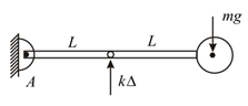
Given:
Mass of attached sphere is
Spring constant is
Vertical deflection is
Maximum amplitude of deflection is
Frequency of rotation is
Concept used:
Draw the FBD for bar AB in equilibrium state.
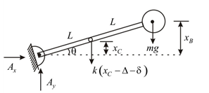
After giving small deflection to bar AB, Draw FBD of bar AB
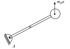
Draw the equivalent kinetic diagram for bar AB as.
Write the expression for displacement of point C in terms of angular displacement.
Here,
Write the expression for displacement of point B in terms of angular displacement.
Here,
Substitute
Take moment about point A for equilibrium position.
For static equilibrium substitute
Simplify the above expression.
Here,
Take moment about point A after giving the angular displacement.
Substitute
Substitute
Substitute
Substitute
Substitute
Rearrange the above expression as.
Here,
Write the standard equation of motion as.
Compare the coefficient of
Compare the coefficient of
Write the expression for maximum amplitude of force.
Here,
Write the expression for natural frequency of system.
Here,
Write the expression for the amplitude of vibration of sphere B.
Here,
Write the expression for magnitude of maximum angular velocity of bar AB.
Here,
Calculation:
Substitute
Substitute
Substitute
Substitute
Substitute
Substitute
The maximum angular velocity of bar AB is
Conclusion:
Thus, the maximum angular velocity of bar AB is
(b)
Magnitude of maximum acceleration of sphere
Answer to Problem 19.107P
The maximum acceleration of sphere is
Explanation of Solution
Concept used:
Write the expression for maximum acceleration of sphere.
Here,
Calculation:
Substitute
The maximum acceleration of sphere is
Conclusion:
Thus, the maximum acceleration of sphere is
Want to see more full solutions like this?
Chapter 19 Solutions
Vector Mechanics For Engineers


- A radius drum is connected to a disk of radius ra. The combined mass of the disc and the drum is m and the combined radius of rotation (radius of inertia) is k and is suspended by two cables.Knowing that the force in the wires is Ta and, determine the accelerations of points A and B on the wire? (m6 kg ra=0,160 rb = 0,210 k = 0,125 ta= 75 tb= 50)arrow_forwardA slender 12.7-kg rod can rotate in a vertical plane about a pivot at A. A spring of constant k= 89 N/m and of unstretched length 350 mm is attached to the rod as shown. Knowing that the rod is released from rest in position (1) (0 = 0°), it has rotated through 90° to reach position (2) (0 = 90°). 400 mm 0=0 200 mm 300 mm 200 mm 0=90 kinetic energy at position (1) (Joules) moment of inertia about the hinge (kg.m²) a. 0.8 о Б.0.97 c. 0.64 d. 1.13 е. 0.32 work due weight (N.m) wwwarrow_forwardA 48-kg advertising panel of length 2a = 2.4 m and width 2b = 1.6 m is kept rotating at a constant rate w1 about its horizontal axis by a small electric motor attached at A to frame ACB. This frame itself is kept rotating at a constant rate w2 about a vertical axis by a second motor attached at C to the column CD. Knowing that the panel and the frame complete a full revolution in 6 s and 12 s, respectively, express, as a function of the angle 0, the dynamic reaction exerted on column CD by its support at D.arrow_forward
- A slender 12.7-kg rod can rotate in a vertical plane about a pivot at A. A spring of constant k= 121 N/m and of unstretched length 370 mm is attached to the rod as shown. Knowing that the rod is released from rest in position (1) (0 = 0°), it has rotated through 90° to reach position (2) ( e = 90°). 400 mm K -0=0 200 mm B 300 mm 200 mm 0=90 kinetic energy at position (1) (Joules) moment of inertia about the hinge (kg.m2) a. 0,8 O b. 0.97 c. 0.64 d. 1.13 O e. 0.32 work due weight (N.m) work due to spring (N.m) a. -5,57 b. -6.68 C. -4.45 d. -7.79 e. -2.23 angular velocity in position (2) (rad/s) О а. 5.71 b. 6.85 C. 4.57 d. 7,99 O e. 2.28 O o o C ооarrow_forward4. The link EF of mass 2 kg is welded at point A to a link ABC of mass 2 kg, which rotates about a pivot B. A spring of constant k =300 N/m and of un-stretched length 150 mm is attached to the link ABC as shown. Knowing that in the position shown the assembly has an angular velocity of 10 rad/s clockwise, (a) Determine the angular velocity when the assembly has rotated 90° clockwise, (b) Find the corresponding angular acceleration of part (a), and (c) Find the corresponding reaction force at point B. (For (b) and (c), set up all the required equations with a Free-Body-Diagram 150 mm and a Kinetic Diagram) 150 mm, 150 mm, E 150 mm 360 mmarrow_forwardA shaft turning at a uniform speed carries two uniform discs A and B of masses 10kg and 8kg respectively. The centres of the mass of the discs are each 2.5mm from the axis of rotation. The radii to the centres of mass are at right angles. The shaft is carried in bearings C and D between A and B such that AC = 0.3m, AD = 0.9m and AB = 1.2m. It is required to make dynamic loading on the bearings equal and a minimum for any given shaft speed by adding a mass at a radius 25mm in a plane E. Determine: The dynamic loading on each bearing when the mass in plane E has been attached and the shaft rotates at 200 rev/min. For the bearing loads in the opposite direction determine all the unknown values. For the bearing loads in the same direction, show the diagrams and equations only to use for a possible solution. PS – Use graphical methods to solve the balancing problemarrow_forward
- Two uniform cylinders, each of weight W=14 lb and radius r = 5 in, are connected by a belt as shown. Knowing that at the instant shown the angular velocity of cylinder A is 30 rad/sec counterclockwise, determine (a) the time required for the angular velocity of cylinder A to be reduced to 5 rad/sec, (b) the tension in the portion of belt between the two cylinders. *** Solve using the method of impulse-momentum *** Barrow_forwardA shaft turning at a uniform speed carries two uniform discs A and B of masses 10kg and 8kg respectively. The centres of the mass of the discs are each 2.5mm from the axis of rotation. The radii to the centres of mass are at right angles. The shaft is carried in bearings C and D between A and B such that AC = 0.3m, AD = 0.9m and AB = 1.2m. It is required to make dynamic loading on the bearings equal and a minimum for any given shaft speed by adding a mass at a radius 25mm in a plane E. Determine: The magnitude of the mass in plane E and its angular position relative to the mass in plane A The distance of the plane E from plane A PS – Use graphical methods to solve the balancing problemarrow_forwardA shaft turning at a uniform speed carries two uniform discs A and B of masses 10kg and 8kg respectively. The centres of the mass of the discs are each 2.5mm from the axis of rotation. The radii to the centres of mass are at right angles. The shaft is carried in bearings C and D between A and B such that AC = 0.3m, AD = 0.9m and AB = 1.2m. It is required to make dynamic loading on the bearings equal and a minimum for any given shaft speed by adding a mass at a radius 25mm in a plane E. Determine: (a) The magnitude of the mass in plane E and its angular position relative to the mass in plane A (b) The distance of the plane E from plane A (c) The dynamic loading on each bearing when the mass in plane E has been attached and the shaft rotates at 200 rev/min. For the bearing loads in the opposite direction determine all the unknown values. For the bearing loads in the same direction, show the diagrams and equations only to use for a possible solution.arrow_forward
- A shaft turning at a uniform speed carries two uniform discs A and B of masses 10kg and 8kg respectively. The centres of the mass of the discs are each 2.5mm from the axis of rotation. The radii to the centres of mass are at right angles. The shaft is carried in bearings C and D between A and B such that AC = 0.3m, AD = 0.9m and AB = 1.2m. It is required to make dynamic loading on the bearings equal and a minimum for any given shaft speed by adding a mass at a radius 25mm in a plane E. Determine: (a) The magnitude of the mass in plane E and its angular position relative to the mass in plane (b) The distance of the plane E from plane A (c) The dynamic loading on each bearing when the mass in plane E has been attached and the shaft rotates at 200 rev/min. For the bearing loads in the opposite direction determine all the unknown values. For the bearing loads in the same direction, show the diagrams and equations only to use for a possible solution. PS - Use graphical methods to solve the…arrow_forwardA shaft turning at a uniform speed carries two uniform discs A and B of masses 10kg and 8kg respectively. The centres of the mass of the discs are each 2.5mm from the axis of rotation. The radii to the centres of mass are at right angles. The shaft is carried in bearings C and D between A and B such that AC = 0.3m, AD = 0.9m and AB = 1.2m. It is required to make dynamic loading on the bearings equal and a minimum for any given shaft speed by adding a mass at a radius 25mm in a plane E. Determine: The magnitude of the mass in plane E and its angular position relative to the mass in plane A The distance of the plane E from plane A The dynamic loading on each bearing when the mass in plane E has been attached and the shaft rotates at 200 rev/min. For the bearing loads in the opposite direction determine all the unknown values. For the bearing loads in the same direction, show the diagrams and equations only to use for a possible solution. PS – Use graphical methods to solve the…arrow_forwardA shaft turning at a uniform speed carries two uniform discs A and B of masses 10kg and 8kg respectively. The centres of the mass of the discs are each 2.5mm from the axis of rotation. The radii to the centres of mass are at right angles. The shaft is carried in bearings C and D between A and B such that AC = 0.3m, AD = 0.9m and AB = 1.2m. It is required to make dynamic loading on the bearings equal and a minimum for any given shaft speed by adding a mass at a radius 25mm in a plane E. USING THE METHOD OF DRAWING m*r and m*r*l diagram Determine: The magnitude of the mass in plane E and its angular position relative to the mass in plane A The distance of the plane E from plane A The dynamic loading on each bearing when the mass in plane E has been attached and the shaft rotates at 200 rev/min. For the bearing loads in the opposite direction determine all the unknown values. For the bearing loads in the same direction, show the diagrams and equations only to use for a possible…arrow_forward
 Elements Of ElectromagneticsMechanical EngineeringISBN:9780190698614Author:Sadiku, Matthew N. O.Publisher:Oxford University Press
 Mechanics of Materials (10th Edition)Mechanical EngineeringISBN:9780134319650Author:Russell C. HibbelerPublisher:PEARSON
 Thermodynamics: An Engineering ApproachMechanical EngineeringISBN:9781259822674Author:Yunus A. Cengel Dr., Michael A. BolesPublisher:McGraw-Hill Education
 Control Systems EngineeringMechanical EngineeringISBN:9781118170519Author:Norman S. NisePublisher:WILEY
 Mechanics of Materials (MindTap Course List)Mechanical EngineeringISBN:9781337093347Author:Barry J. Goodno, James M. GerePublisher:Cengage Learning
 Engineering Mechanics: StaticsMechanical EngineeringISBN:9781118807330Author:James L. Meriam, L. G. Kraige, J. N. BoltonPublisher:WILEY