
University Physics Volume 2
18th Edition
ISBN: 9781938168161
Author: OpenStax
Publisher: OpenStax
expand_more
expand_more
format_list_bulleted
Videos
Textbook Question
Chapter 14, Problem 53P
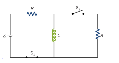
For the circuit shown below,
Expert Solution & Answer
Want to see the full answer?
Check out a sample textbook solution
Students have asked these similar questions
For the circuit shown below, E = 26 V, L = 2.4 mH, and R = 4.5 n. After steady state is reached with s, closed and s, open, S, is closed and immediately thereafter (at t = 0) s, is opened.
R
(a) Determine the current through L (in A) at t = 0.
A
(b) Determine the current through L (in A) at t = 4.0 x 10⁴ s
(c) Determine the voltages across L and R (in V) at t = 4.0 x 10* s.
V, =
VR =
For the circuit shown below, ε = 24 V, L = 6 mH, and
R = 4.50. After steady state is reached with S₁ closed and
S₂ open, at t = 0, S₂ is closed and S₁ is opened. Determine
(a) the current through L at t = 0, (b) the current through L
at t = 5.5 x 10⁻⁴ s, (c) the voltage across R on the right
at t = 5.5 × 10⁻⁴ s, and (d) the rate at which current
through I changes at t = 5.5 × 10⁻⁴
L
S.
E
Hint
R
S₁
eeee
a. The current through L at t = 0 is
5.3
A. Additional Hints
for (a).
b. The current through Lat t = 5.5 x 10⁻⁴ s is
A. Additional Hints
for (b).
c. The voltage across R at t = 5.5 x 10⁻⁴ s is
V. Additional Hints
for (c).
d. The rate at which current through L changes at
t = 5.5 × 10⁻⁴ s is
A/s. Additional Hints for (d).
21 V, L
0, S2 is closed and S1 is opened. Determine (a) the current through L at
For the circuit shown below, ɛ
Si closed and S2 open, at t
t = 0, (b) the current through L at t
t = 3 x 10⁻⁴
4.5 mH, and R = 4N. After steady state is reached with
3 x 10
s, (c) the voltage across R on the right at
s, and (d) the rate at which current through L changes att = 3 x 10⁻⁴ s.
R
E
.R
Hint
a. The current through L at t = 0 is 5.25
A. Additional Hints for (a)
.4
b. The current through L at t = 3 x 10
s is 4.0211
A. Additional Hints for (b)
- 4
c. The voltage across R att
3 x 10
s is 16.17
V. Additional Hints for (c)
d. The rate at which current through L changes at t = 3 × 10°
s is
A/s.
Additional Hints for (d).
0000
Chapter 14 Solutions
University Physics Volume 2
Ch. 14 - Check Your Understanding. A current...Ch. 14 - Check Your Understanding. Current flows through...Ch. 14 - Check Your Understanding. A changing current...Ch. 14 - Check Your Understanding (a) Calculate the...Ch. 14 - Check Your Understanding (a) What is the magnetic...Ch. 14 - Check Your Understanding How much energy is stored...Ch. 14 - Check Your Understanding Verify that RC and L/R...Ch. 14 - Check Your Understanding (a) If the current in the...Ch. 14 - Check Your Understanding For the circuit of in...Ch. 14 - Check Your Understanding The angular frequency of...
Ch. 14 - Check Your Understanding In an RLC circuit, L =...Ch. 14 - Show that N m /l and el(dl/dt), which are both...Ch. 14 - A 10-H inductor carries a current of 20 A....Ch. 14 - The ignition circuit of an automobile is powered...Ch. 14 - When the current through a large inductor is...Ch. 14 - Does self-inductance depend on the value of the...Ch. 14 - Would the self-inductance of a 1.0 m long, tightly...Ch. 14 - Discuss how you might determine the-inductance per...Ch. 14 - The self-inductance of a coil is zero if there is...Ch. 14 - How does the self- inductance per unit length near...Ch. 14 - Solve that I I 2 /2 has units of energy.Ch. 14 - Use Lenz’s law to explain why the initial current...Ch. 14 - When the current in the RL circuit of Figure...Ch. 14 - Does the time required for the current in an RL...Ch. 14 - An inductor is connected across the terminals of a...Ch. 14 - At what time is the voltage across the inductor of...Ch. 14 - In the simple RL circuit of Figure 14.12(b), can...Ch. 14 - If emf of the battery of Figure 14.12(b) is...Ch. 14 - A steady current flows through a circuit with a...Ch. 14 - Describe how the currents through R1and R2, shown...Ch. 14 - Discuss possible practical applications of RL...Ch. 14 - Do Kirchhoff’s rules apply to circuits that...Ch. 14 - Can a circuit e1eent have both capacitance and...Ch. 14 - In an LC circuit, what determines the frequency...Ch. 14 - When a wire is connected between the two ends of a...Ch. 14 - Describe what effect the resistance of the...Ch. 14 - Suppose you wanted to design an LC circuit with a...Ch. 14 - A radio receiver uses an RLC circuit to pick out...Ch. 14 - When the current in one coi1 changes at a rate of...Ch. 14 - An emf of 9.7 × 10⁻³ V is induced in a coil while...Ch. 14 - Two coils close to each other have a mutual...Ch. 14 - A coil of 40 turns is wrapped around a long...Ch. 14 - A 600-turn solenoid is 0.55 m long and 4.2 cm in...Ch. 14 - A toroidal coil has a mean radius of 16 cm and a...Ch. 14 - A solenoid of N1turns has length l1and radius R1,...Ch. 14 - An emf of 0.40 V is induced across a coil when the...Ch. 14 - The current shown in part (a) below is increasing,...Ch. 14 - What is the rate at which the current though a...Ch. 14 - When a camera uses a flash, a fully charged...Ch. 14 - A coil with a self-inductance of 2.0 H carries a...Ch. 14 - A solenoid 50 cm long is wound with 500 turns of...Ch. 14 - A coil with a self-inductance of 3.0 H carries a...Ch. 14 - The current I(t) through a 5.0-mH inductor varies...Ch. 14 - A long, cylindrical solenoid with 100 turns per...Ch. 14 - Suppose that a rectangular toroid has 2000...Ch. 14 - What is the self-inductance per meter of a coaxial...Ch. 14 - At the instant a current of 0.20 A is flowing...Ch. 14 - Suppose that a rectangular toroid has 2000...Ch. 14 - Solenoid A is tightly wound while solenoid B has...Ch. 14 - A 10-H inductor carries a current of 20 A. How...Ch. 14 - A coil with a self-inductance of 3.0 H and a...Ch. 14 - A current of 1.2 A is flowing in a coaxial cable...Ch. 14 - In Figure 14.12, =12V , L = 20 mH, and R=5.0....Ch. 14 - For the circuit shown below, =20V , L = 4.0 mH,...Ch. 14 - The current in the RL circuit shown here increases...Ch. 14 - How long after switch S1 is thrown does it take...Ch. 14 - Examine the circuit shown below in part (a)....Ch. 14 - The current in the RL circuit shown below reaches...Ch. 14 - Consider the circuit shown below. Find l1, l2and...Ch. 14 - For the circuit shown below, =50V , R1= 10 , and...Ch. 14 - For the circuit shown below, find the current...Ch. 14 - Show that for the circuit shown below, the initial...Ch. 14 - A 5000-pF capacitor is charged to 100 V and then...Ch. 14 - The self-inductance and capacitance of an LC...Ch. 14 - What is the self-inductance of an LC circuit that...Ch. 14 - In an oscillating LC circuit the maximum charge on...Ch. 14 - The self-inductance and capacitance of an...Ch. 14 - In an oscillating LC circuit, the maximum charge...Ch. 14 - In the circuit shown below, S1is opened and S2is...Ch. 14 - An LC circuit in an AM tuner (in a car stereo)...Ch. 14 - In an oscillating RLC circuit, R=5.0 ,. L=5.0mH ,...Ch. 14 - In an oscillating RLC circuit with L = 10 mH, C =...Ch. 14 - What resistance R must be connected in series with...Ch. 14 - Show that the self-inductance per unit length of...Ch. 14 - Two long, parallel wires cy equal currents in...Ch. 14 - A small, rectangular single loop of wire with...Ch. 14 - Suppose that a cylindrical solenoid is wrapped...Ch. 14 - A solenoid with 4 x 10⁷turns/m has an iron core...Ch. 14 - A rectangular toroid with inner radius R1= 7.0cm,...Ch. 14 - The switch S of the circuit shown below is closed...Ch. 14 - In an oscillating RLC circuit, R = 7.0 L. = 10...Ch. 14 - A 25.0-H inductor has 100 A of current turned off...Ch. 14 - A coaxial cable has an inner conductor of radius...Ch. 14 - In a damped oscillating circuit the energy is...Ch. 14 - The switch in the circuit shown below is closed at...Ch. 14 - A square loop of side 2 cm is placed 1 cm from a...Ch. 14 - A rectangular copper ring, of mass 100 g and...
Additional Science Textbook Solutions
Find more solutions based on key concepts
64. In the laboratory, endothermic reactions are usually preformed at elevated temperatures, whereas exothermic...
Conceptual Physical Science (6th Edition)
60. During a violent electrical storm, a car is struck by a falling high-voltage wire that puts an excess charg...
College Physics (10th Edition)
Choose the best answer to each of the following. Explain your reasoning. The luminosity of a quasar is generate...
The Cosmic Perspective Fundamentals (2nd Edition)
18.28 A flask contains a mixture of neon (Ne), krypton (Kr), and radon (Rn) gases. Compare (a) the average kine...
University Physics (14th Edition)
The specific heat capacity of Albertsons Rotini Tricolore is approximately 1.8J/gC. Suppose you toss 340 g of t...
An Introduction to Thermal Physics
The pV-diagram of the Carnot cycle.
Sears And Zemansky's University Physics With Modern Physics
Knowledge Booster


Learn more about
Need a deep-dive on the concept behind this application? Look no further. Learn more about this topic, physics and related others by exploring similar questions and additional content below.Similar questions
- Two conducting wires A and B of the same length and radius are connected across the same potential difference. Conductor A has twice the resistivity of conductor B. What is the ratio of the power delivered to A to the power delivered to B? (a) 2 (b) 2 (c) 1 (d) 12 (e)12arrow_forwardA capacitor with initial charge Q0 is connected across a resistor R at time t = 0. The separation between the plates of the capacitor changes as d = d0/(1 + t) for 0 t 1 s. Find an expression for the voltage drop across the capacitor as a function of time.arrow_forwardFor the circuit shown below, ε=22 V, L=7.5 mH, and R=6Ω. After steady state is reached with S1 closed and S2 open, at t=0, S2 is closed and S1 is opened. Determine (a) the current through L at t=0, (b) the current through L at t=4.5×10⁻⁴ s, (c) the voltage across R on the right at t=4.5×10⁻⁴ s, and (d) the rate at which current through L changes at t=4.5×10⁻⁴ s. The current through L at t=0 is__________A. The current through L at t=4.5×10⁻⁴ s is_____A. The voltage across R at t=4.5×10⁻⁴ s is______V. The rate at which current through L changes at t=4.5×10⁻⁴ s is______A/s.arrow_forward
- In the circuit shown in the figure, the S switch closed at t=0 and the capacitors, which are completely empty, begin to fill. Here ε=10 V, C=5 μF and R=55 Ω. What is the time constant of the circuit, τ, in units of microseconds? When t= τ, what is the total charge, in units of microcoulomb, accumulated in the capacitors?arrow_forward3 0 b In the circuit shown, Determine the following: a 7 V 2 V+ A. Magnitude and direction of the current (Ans. I = 0.3889 A, CCW) B. The potential differences Vaa, Ver and Vne (Ans. Vad = 7.8333 V, Vef = -1.8889 V, Vne 4. 3333 V) h 6 V |+ 6Ω 4 V g + f earrow_forwardA cell of e.m.f. 1.5 V and internal resistance 1.0 N maintains a constant current of 0.5 A in an external circuit. When an electric charge of 2.0 C flows in the external circuit, calculate (a) (b) (c) the thermal energy dissipated from the cell. the energy dissipated from the external circuit. the total energy supplied by the cell. [Ans: 1.0 J, 2. 0 J, 3. 0 J ] 4-arrow_forward
- For the circuit shown in Fig. Q1(c), the capacitor is initially charged to 2.5 V with the polarity shown. Calculate the voltage vc (t) when the switch (S) is closed. + 7.5 V R, Σ 3.3 ΚΩ R₂ 9.5 ΚΩ S 42 uF - 15 V Fig. Q1(c)arrow_forwardFor the circuit shown in the figure, V = 20 V, C = 10 μF, R = 0.80 MQ, and the battery is ideal. Initially the switch S is open and the capacitor is uncharged. The switch is then closed at time t = 0.00 s. What is the charge across the capacitor 20 s after closing the switch? { www R O 0.18 mC O 1.5 mC O 0.48 mC O 3.0 MC O 2.3 MCarrow_forward() THE FOLLOWING QUESTIONS ARE BASED ON THE INFORMATION GIVEN HERE. C. In the circuit shown in the figure, the S switch is closed att= 0 and the capacitors, which are completely empty, begin to fill. Here &= 25 V, C = 7µF and R 20 2. A) What is the time constant of the circuit, T, in units of microseconds? Answer: B) When t = T, what is the total charge, in units of microcoulomb, accumulated in the capacitors? Answer:arrow_forward
- (a) Calculate the magnitude (in A) and indicate the direction of flow of current in the figure below. E₂ = 23.0 V and r₂ = 0.70 0. magnitude direction E₁ = 12.0 V = = η = 1.0 Ω |--Select-- (b) Find the terminal voltage (in V) of each battery. V₁ V V₂ A V E2 = 18.0 V 1 = 0.5 Ω Are their values consistent with the direction of current flow? O Noarrow_forwardA circuit consists of a resistor R1 = 126 Ω, a resistor R2 = 275 Ω, a capacitor C = 182 mF, a switch, and an e = 3.00-Vbattery, all connected in series. Initially the capacitor is uncharged and the switch is open. At time t = 0 the switch isclosed. (a) What charge will the capacitor have a long time after the switch is closed? (b) At what time will the chargeon the capacitor be 80.0% of the value found in part (a)?arrow_forward3 0 a b C In the circuit shown, Determine the following: 7 V 2 v+ A. Magnitude and direction of the current (Ans. I = 0.3889 A, CCW) B. The potential differences Vad, Vef and Vhe (Ans. Vad = 7.8333 V, Vef =-1.8889 V, Vhe 4.3333 V) %3D %3D %3D h d. 6 V+ 60 4 V e + farrow_forward
arrow_back_ios
SEE MORE QUESTIONS
arrow_forward_ios
Recommended textbooks for you

 Principles of Physics: A Calculus-Based TextPhysicsISBN:9781133104261Author:Raymond A. Serway, John W. JewettPublisher:Cengage Learning
 College PhysicsPhysicsISBN:9781305952300Author:Raymond A. Serway, Chris VuillePublisher:Cengage Learning
 College PhysicsPhysicsISBN:9781285737027Author:Raymond A. Serway, Chris VuillePublisher:Cengage Learning
 Physics for Scientists and Engineers: Foundations...PhysicsISBN:9781133939146Author:Katz, Debora M.Publisher:Cengage Learning
 Physics for Scientists and Engineers, Technology ...PhysicsISBN:9781305116399Author:Raymond A. Serway, John W. JewettPublisher:Cengage Learning
Principles of Physics: A Calculus-Based Text
Physics
ISBN:9781133104261
Author:Raymond A. Serway, John W. Jewett
Publisher:Cengage Learning
College Physics
Physics
ISBN:9781305952300
Author:Raymond A. Serway, Chris Vuille
Publisher:Cengage Learning
College Physics
Physics
ISBN:9781285737027
Author:Raymond A. Serway, Chris Vuille
Publisher:Cengage Learning
Physics for Scientists and Engineers: Foundations...
Physics
ISBN:9781133939146
Author:Katz, Debora M.
Publisher:Cengage Learning
Physics for Scientists and Engineers, Technology ...
Physics
ISBN:9781305116399
Author:Raymond A. Serway, John W. Jewett
Publisher:Cengage Learning
DC Series circuits explained - The basics working principle; Author: The Engineering Mindset;https://www.youtube.com/watch?v=VV6tZ3Aqfuc;License: Standard YouTube License, CC-BY