
Concept explainers
Videos
(a) Determine s on the transmission line of Figure 10.32. Note that the dielectric is air. (b) Find the input impedance. (c) If
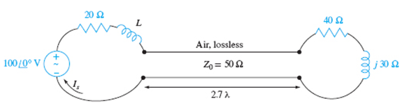
Figure 10.32 See Problem 10.20.
(a)
The value ofs on the transmission line.
Answer to Problem 10.20P
The value of son the transmission line is 2.
Explanation of Solution
Given:
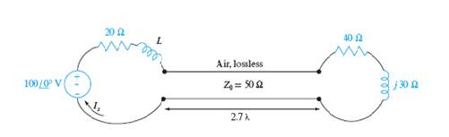
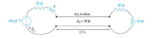
The given figure is shown below.

Concept Used:
The term s is calculated by
Calculation:
The reflection coefficient is
The magnitude of the reflection coefficient is,
The standing wave ratio is calculated as
Conclusion:
The value of s in the transmission line is 2.
(b)
The input impedance.
Answer to Problem 10.20P
The input impedance of the transmission line is
Explanation of Solution
Given:
The given figure is shown below.
Concept Used:
The input impedance is calculated by
Calculation:
The input impedance of the transmission line is calculated as
Let
Conclusion:
The input impedance of the transmission line is
(c)
The source current
Answer to Problem 10.20P
The source current is
Explanation of Solution
Given:

Calculation:
The source current is calculated by
Let
Conclusion:
Thus, the source current is
(d)
The value of L which produces maximum value for
Answer to Problem 10.20P
The value of L which produces maximum value for
Explanation of Solution
Given:
The given circuit is shown below.
Concept Used:
The maximum value of L is calculated by
Calculation:
The magnitude of the source current is,
Differentiating with respect to L,
Conclusion:
The value of L which produces maximum value for
(e)
The average power delivered by the source.
Answer to Problem 10.20P
The average power delivered by the source is,
Explanation of Solution
Given:
The given circuit is shown below.

Concept Used:
The average power is calculated by
Calculation:
Considering the real part only
Average power is calculated as
Conclusion:
Thus, the average power delivered by the source is,
(f)
Average power delivered to ZL.
Answer to Problem 10.20P
The average power delivered to the load is
Explanation of Solution
Given:

Concept Used:
The average power delivered is calculated by
Calculation:
Thus, the total power delivered to the load is
Conclusion:
Thus, the average power delivered to the load is
Want to see more full solutions like this?
Chapter 10 Solutions
Engineering Electromagnetics


- For the given circuit, calculate the cutoff frequency (f) by means of Hertz assuming that R1=3 kN,C= 2.5 µF, R2= 0.9 kQ. R1 Vi C R2 Vo Remark1: Only numeric values must be entered. Do not enter the units. Remark2: Use maximum one digit after dot. Round the numbers as provided below. (ex: If you calculate 10.83 , write 10.8, not 11) (ex: if you calculate 15.67 , write 15.7, not 16) (ex: if you calculate 18.98 , write 19) Remark3: Don't use comma (ex: Write 50.6, not 50,6)arrow_forwardCalculate the average power value of X (n) =5cos(n. π /6) + 6 as defined in discrete time?? I would be happy if you help:)arrow_forwardRequired information NOTE: This is a multi-part question. Once an answer is submitted, you will be unable to return to this part. Consider the following figure. 110 10 92 2592 The circuit shown in the given figure is represented in the phasor (frequency) domain. If 10 = 9235° A, V = 10/35°, and I = 2/35⁰ A. Across what type of element does V appear, and what is its value? (You must provide an answer before moving on to the next part.) The solution is Ω.arrow_forward
- An FM signal has a deviation of 3 kHz and a modulating frequency of 1 kHz. Its total power is 5 W, developed across a 50 2 resistive load. The carrier fre- quency is 160 MHz. (a) Calculate the RMS signal voltage. (b) Calculate the RMS voltage at the carrier frequency and each of the first three sets of sidebands. (c) Calculate the frequency of each sideband for the first three sideband pairs. es Falerna avlop (d) Calculate the power at the carrier frequency, and in each sideband, for the first three pairs.arrow_forwardA sinusoidal modulating waveform of amplitude 5v and a frequency of 2KHZ is applied to FM generator, which has a frequency sensitivity of 40Hz/Volt. Evalulate: Frequency deviation, modulation index, Bandwidtharrow_forward10.1 Sketch and fully label the impedance diagram (also show the exact value for the magnitude and phase angle of Zt) for the following expression: Zt = 20 – j455 ohm.arrow_forward
- In the circuit shown in Figure 10.29, find the transfer function H(o)= Vo/Vin. с HH 0.25 F in Figure 10.29 a. H(o)= b. H(o)= c. H (@) = R₁ 492 d. H(@) = L 0.5 H R₂ ΖΩ (1/3) (jw)² (ja)²+(10/3) jo+6 (1/3)(jw)² (jo)² + (10/3) jo+5 (1/3)(jw)² (jo)² + (10/3) jo+17/3 (1/3)(jw)² (jo)² + (10/3) jo+16/3 +arrow_forwardB) An FM signal e(t)FM = 20 cos (210¹t+ 6 sin 2x10³) exist over 5002 resistive load, determine: 1. Total output power. 2. The amplitude of the third sideband. 3. The percentage power of fifth sideband to the total output power. 4. The Max. frequency deviation. 5. The BW required to transmit this signal. J. Js Bessel Table J6 J7 J8 J9 J10 J11 J12 J13 J14 J15 J16 B Jo 0.00 1.00 1.00 0.77 0.44 0.11 0.02 2.00 0.22 0.58 0.35 0.13 0.03 3.00 -0.26 0.34 0.49 0.31 0.13 0.04 0.01 4.00 -0.40 -0.07 0.36 0.43 0.28 0.13 0.05 0.02 - 0.13 0.05 0.02 5.00 -0.18-0.33 0.05 0.36 0.39 0.26 6.00 0.15 -0.28 -0.24 0.11 0.36 0.36 0.25 0.13 0.06 0.02 7.00 0.30 0.00 -0.30 -0.17 0.16 0.35 0.34 0.23 0.13 0.06 0.02 - 8.00 0.17 0.23 -0.11 -0.29 -0.10 0.19 0.34 0.32 0.22 0.13 0.06 0.03arrow_forward1. You are given an equation: 100 cos[(2π x 105 t) + 35 cos(100πt)]. From this expression, Determine the a)peak frequency deviation, b) carrier swing, c)practical bandwidth and d) Carson's rule bandwidtharrow_forward
- 3. From the figure shown. a. Calculate 5T. b. Compare 5T to half the period of the applied signal. c. Sketch v .. + ai uF Si 56 ka -12 V Note: The time constant of the discharging network is determined by the product RC and has the magnitude t = RCarrow_forwardQ. The two – sided exponential voltage f(t) = Be-Ale| volt is developed across a 1 2 resistor. 1- Calculate the total energy dissipated in the resistor. 2- What fraction of this energy is in the frequency range of 0 - C rad/sec? when A=29 B=58 C=41arrow_forwardAn e.m.f. “e" is given by: e = 40 + 150Sinωt + 30Sin(2ωt-π/4) + 10Sin(4ωt-π/3) +⋯volts With a fundamental frequency of 50 Hz, “e” supplies a series connection of a 100 ohms resistor and 15µF capacitor. Determine a. The r.m.s. value of the voltage b. The amplitude of the second harmonic of the circuit current c. The phase angle of the fourth harmonic of the current d. The r.m.s. value of the circuit current e. The apparent power consumed by the circuit f. The overall power factorarrow_forward
 Introductory Circuit Analysis (13th Edition)Electrical EngineeringISBN:9780133923605Author:Robert L. BoylestadPublisher:PEARSON
 Delmar's Standard Textbook Of ElectricityElectrical EngineeringISBN:9781337900348Author:Stephen L. HermanPublisher:Cengage Learning
 Programmable Logic ControllersElectrical EngineeringISBN:9780073373843Author:Frank D. PetruzellaPublisher:McGraw-Hill Education
 Fundamentals of Electric CircuitsElectrical EngineeringISBN:9780078028229Author:Charles K Alexander, Matthew SadikuPublisher:McGraw-Hill Education
 Electric Circuits. (11th Edition)Electrical EngineeringISBN:9780134746968Author:James W. Nilsson, Susan RiedelPublisher:PEARSON
 Engineering ElectromagneticsElectrical EngineeringISBN:9780078028151Author:Hayt, William H. (william Hart), Jr, BUCK, John A.Publisher:Mcgraw-hill Education,