
Concept explainers
Videos
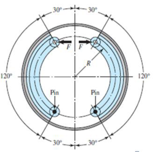
The figure shows an internal rim-type brake having an inside rim diameter of 300 mm and a dimension R = 125 mm. The shoes have a face width of 40 mm and are both actuated by a force of 2.2 kN. The drum rotates clockwise. The mean coefficient of friction is 0.28.
- (a) Find the maximum pressure and indicate the shoe on which it occurs.
- (b) Estimate the braking torque effected by each shoe, and find the total braking torque.
- (c) Estimate the resulting hinge-pin reactions.
Problem 16-1
(a)
The maximum pressure.
The shoe on which maximum pressure occurs.
Answer to Problem 1P
The maximum pressure is
The shoe on which maximum pressure occurs is right side.
Explanation of Solution
Write the expression for moment of frictional forces.
Here, coefficient of friction is
Write the expression for moment of normal forces.
Here, moment of normal forces is
Write the expression for actuating force.
Here, actuating force is
Write the expression for actuating force in reversed rotation.
Conclusion:
Substitute
Substitute
Substitute
Substitute
Since the maximum pressure occur on the right side of the shoe. So the maximum pressure occurs on the right shoe.
Thus, the maximum pressure is
(b)
The braking torque effected by right shoe.
The braking torque effected by left shoe.
The total braking torque.
Answer to Problem 1P
The braking torque effected by right shoe is
The braking torque effected by left shoe is
The total braking torque is
Explanation of Solution
Write the expression for torque applied by the right hand shoe.
Here, braking torque on right hand side shoe is
Write the expression\n for braking torque on left hand side shoe.
Here, braking torque on left hand side shoe is
Write the expression for total braking torque.
Here, total braking torque is
Conclusion:
Substitute
Thus, braking torque on right hand side shoe is
Substitute
Thus, braking torque on left hand side shoe is
Substitute
Thus, the total torque is
(c)
The resulting hinge pin reaction at right hand shoe.
The resulting hinge pin reaction at left hand shoe.
Answer to Problem 1P
The resulting hinge pin reaction at right hand shoe is
The resulting hinge pin reaction at left hand shoe is
Explanation of Solution
Write the expression for force in horizontal direction for right hand shoe.
Here, horizontal force is
Write the expression for vertical direction force on right hand side shoe.
Here, vertical direction force is
Write the expression for horizontal reaction for right hand side shoe.
Here, reaction in horizontal direction is
Write the expression for reaction in vertical direction for right hand side shoe.
Here, reaction in vertical direction for left hand shoe is
Write the expression for resultant reaction.
Write the expression for force in horizontal direction for left hand shoe.
Here, horizontal force is
Write the expression for vertical direction force on left hand side shoe.
Here, vertical direction force is
Write the expression for horizontal reaction for left hand side shoe.
Here, reaction in horizontal direction is
Write the expression for reaction in vertical direction for left hand side shoe.
Here, reaction in vertical direction for right hand shoe is
Conclusion:
Substitute
Substitute
Substitute
Substitute
Substitute
The resulting hinge pin reaction at right hand shoe is
Substitute
Substitute
Substitute
Substitute
Substitute
Thus the resultant reaction on left hand side shoe is
Want to see more full solutions like this?
Chapter 16 Solutions
Shigley's Mechanical Engineering Design (McGraw-Hill Series in Mechanical Engineering)


- 50 mm and the coefficient of friction between the blocks and the drum is 0.25. 30° Q9/ braking system has its braking lever inclined at an angle of 30° to the horizontal plane, as shown in Figure. The diameter of the brake drum is 540 mm and rotates clockwise; the angle of contact surface of the block is 50. At the instant the lever is pressed on the brake drum with a vertical force of 600 N. The coefficient of friction between the brake shoe and the brake drum is 0.4. Assume that the lever and brake shoe are perfectly rigid Brake drum- and possess negligible weight. Find the braking torque. -0.4 m- Horizontal plane 0.8 m 600 Narrow_forwardA band brake embraces a 500 mm diameter drum with an angle of lap of 270° and produces a braking torque of 200 Nm. The coefficient of friction is 0.2. One end of the band is attached to the fulcrum pin and the other end is attached to a pin B. Which of the following is the tension in the slack side of the band? 75 -450 C 270° O 280 N O 510N O 255 N 0 445 N All dimensions in mm.arrow_forwardThe band of a brake has a contact angle of 18° deg. If the pulls on the bands are 275 kg and 100 kg, find the coefficient of friction.arrow_forward
- PROBLEMS Problem 1 (Dimensions in mm.) The block-type hand brake shown in the figure has a face width of 30 mm and a mean coefficient of friction of 0.25. For an estimated actuating force of 400 N, find the maximum pressure on the shoe and find the braking torque. 150 + 150R- 200- 90° -300- 45° 4 DIM in mm Rotationarrow_forwardA car engine has its rated output of 120 kW. The maxdmum torque developed is 110 Nm, The clutch used is of single plate type having two active surfaces. Axia! pressure is not to exceed 0.85 bar. External diamater of friction plate is 1.25 times the internal diameter. Determine the dimensions of friction plate and axial force exerted by the spring. Assume uniform wear and coefficient of friction to be 0.3.arrow_forwardConsider the arrangement of a simple band brake as shown in the figure. Determine the brake torque due to load applied at end A. Take the coefficient of friction as 0.22. 1.5 m 0.5 m B Answer Choices: a. 320 N-m b. 120 N-m c. 480 N-m d. 260 N-m 0.3 m 20% P = 250 Narrow_forward
- The forces F, and F, in a brake band and the direction of rotation of the drum are as shown in the figure. The coefficient of friction is 0.25. The angle of wrap is 3n/2 radians. It is given that R = 1 m and F, = 1 N. The torque (in Nm) %3D exerted on the drum is R F2 F,arrow_forwardA block brake with a torque of 250 N-m. Its drum rotates at 100 rpm. The length of the block (1) is twice its width (w). Assume, the coefficient of friction P is 0.35. Calculate: (1) the applied load (P) and the hinge-pin reaction (Rx ana Ry) for clockwise rotation of the drum; (2) the applied load and hinge-pin reaction for anticlockwise rotation of the drum; (3) the rate of heat generated during the braking action. (4) The dimensions of the block, if the intensity of pressure between the block and brake drum is 1 MPa. (5) Check whether the brake is self-locking.arrow_forwardDetermine the principal dimensions of a cone clutch faced with lather to transmit 40 kW at 800 r.p.m. from an electric motor to an air compressor. Sketch a sectional front view of the clutch and provide the main dimensions. Assume that the semi-angle of the cone is 10°, the coefficient of friction is 0.3, mean diameter of cone is (7-10)d, where d is the diameter of the shaft, allowable normal pressure for lather and cast iron is 0.1 to 0.2 N/mm, shear stress 100 N/mm², load factor is 2 and the mean diameter to face width ratio is 6.arrow_forward
- A calliper brake is required for the front wheels of a sport's car with a braking capacity of 890,485 Nm for each brake. Preliminary design estimates have set the brake geometry as r=100 mm, ro=155 mm and 0=45°. A pad with a coefficient of friction of 0,45 has been selected. Determine: 4.1. the required actuating forces, 4.2. the average and maximum contact pressures.arrow_forwardPlease, reaply as soon as posible! Static Problem The band brake shown controls the rotation of the drum. The coefficient of friction between the belt and the drum is 0.25. The weight of the lever is negligible.Determine the force P that must be applied at the end of the braking lever to resist a torque T = 200 lb in, if the torque is applied in the: a) Clockwise b) Counterclockwise direction.arrow_forwardA band brake is to absorb 5 Hp at 200 rpm. The maximum pressure of the lining and the drum is 120 psi. The angle of wrap is 3.6 radians, the width of the band is 3 inches and f = 0.15. Find the forces at the tight side. The diameter of the drum is at 8 inches. The correct answer is 2880 lbs. I just need a complete solution. Thank you!arrow_forward
 International Edition---engineering Mechanics: St...Mechanical EngineeringISBN:9781305501607Author:Andrew Pytel And Jaan KiusalaasPublisher:CENGAGE L